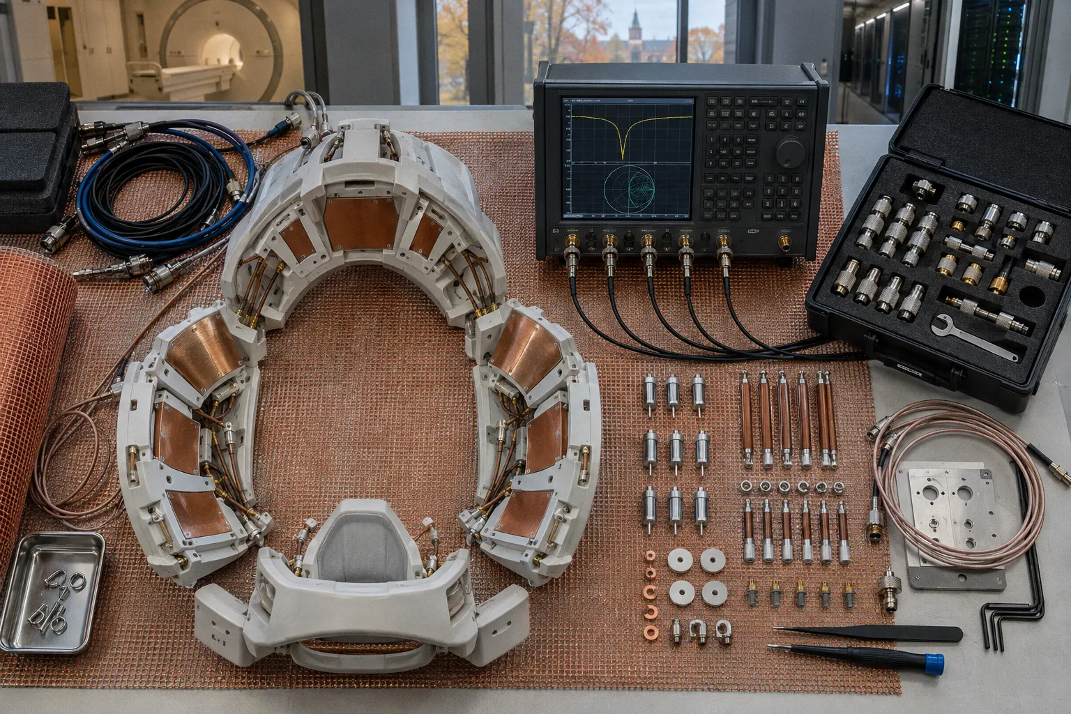
It changes the electrical behavior of the entire RF chain: coil conductors, capacitors, matching networks, cables, patient tissue, and the scanner’s transmit and receive interfaces.
The central problem is direct. The coil must present a controlled impedance to a system designed around a 50 Ω transmission line. A human subject does not provide a fixed load. Body size, tissue composition, anatomy, and positioning alter the sample load. The resonant frequency shifts. The complex input impedance moves. Reflected RF power rises. Flip-angle delivery becomes less predictable. Receive sensitivity can degrade.
Radiofrequency coil impedance matching in 7T MRI is therefore not a final adjustment performed after construction. It is a load-dependent engineering problem. At 298 MHz, the subject is part of the RF circuit.
At 7T, the patient is not merely inside the coil. The patient changes the coil’s electrical boundary conditions.
The physics of 7T resonance and dielectric loading
The proton Larmor frequency increases with magnetic field strength. At 7T, the ¹H resonance is approximately 298 MHz. This places the RF wavelength in tissue within a range where dielectric effects become operationally significant rather than theoretical.
At lower field strengths, many RF coil designs can tolerate a comparatively simple interpretation of loading. The sample absorbs energy, modifies the quality factor, and changes the impedance. At 7T, that description is incomplete. The shorter RF wavelength allows spatial variation in electromagnetic fields across the anatomy. Tissue permittivity and conductivity influence propagation, phase, and local energy deposition.
The coil no longer behaves as an isolated resonant object with a single stable tuning point. It behaves as a coupled electromagnetic structure. The resonant frequency depends on the geometry of the coil and on the electromagnetic properties of the subject placed inside it.
Why 298 MHz changes the engineering problem
An RF coil is a resonant network. Its resonant behavior is determined by inductive and capacitive elements, conductor geometry, losses, and the load presented by the environment. The scanner does not directly “see” an abstract resonance. It sees the impedance at the coil port.
That impedance is complex. It includes a resistive component and a reactive component. The resistive portion represents power dissipation, including losses in conductors, components, and tissue. The reactive portion represents stored electromagnetic energy. If the port impedance is not transformed to the expected system impedance, part of the incident RF wave returns toward the source.
At 7T, subject-dependent effects are amplified by the operating frequency:
- Tissue loading changes the effective resistance presented at the coil port.
- Dielectric loading shifts the resonant frequency.
- Subject position changes the spatial relationship between tissue and RF conductors.
- Anatomical asymmetry produces different loading across coil elements.
- Coupling between adjacent channels can change as the subject enters the coil.
- Local field behavior can vary even when the global port match appears acceptable.
The final point is routinely mishandled. A good input match does not guarantee a uniform transmit field. It does not prove that B1+ is homogeneous. It does not remove localized SAR hot spots. It only establishes that the port-level interaction with the RF system is controlled within the measured condition.
Tuning and matching are separate operations
RF coil tuning and matching are often treated as a single phrase. They are related, but they solve different problems.
Tuning places the resonant behavior of the coil near the target operating frequency. The objective is frequency alignment. If the coil is detuned from approximately 298 MHz, the RF response shifts away from the intended excitation and reception condition.
Matching transforms the coil’s complex input impedance to the characteristic impedance of the scanner transmission line, typically 50 Ω. The objective is power transfer. A coil can be tuned near resonance and still be poorly matched. It can also show an acceptable match at one condition while its resonance shifts under a different subject load.
The distinction matters during both development and clinical operation. A frequency shift points toward a tuning problem, a loading change, or both. A large reflected-power component points toward an impedance transformation problem. These are not interchangeable faults.
Transforming the coil impedance to 50 Ω
The scanner’s RF interface is designed around a characteristic impedance that is typically 50 Ω. The coil, however, rarely presents 50 Ω naturally across all operating conditions. Its raw impedance is shaped by the resonant network and by the subject.
The matching network transforms that raw complex impedance into a value compatible with the transmission line. The transformation may use capacitive elements, inductive elements, or more elaborate networks integrated into the coil architecture. The exact topology depends on the coil geometry, channel count, operating mode, and required bandwidth.
The engineering target is not simply a low numerical value. The target is a controlled complex impedance at the operating frequency, under a defined loading condition.
Forward power, reflected power, and delivery efficiency
When RF power reaches the coil port, it divides conceptually into several paths:
1. Power is transferred into the coil and subject.
2. Power is dissipated in conductors and components.
3. Power is absorbed by tissue.
4. Power is reflected because the input impedance does not match the transmission line.
The scanner can monitor forward and reflected RF power. This measurement provides a direct operational view of how efficiently the transmit chain is delivering energy. It also provides a warning when the coil’s electrical condition has changed.
An impedance mismatch in ultra high field MRI is not merely an efficiency defect. It can affect the relationship between commanded transmit power and the actual RF field produced in the subject. A sequence may request a nominal flip angle, but the delivered B1+ field depends on the coil state, the load, the transmit architecture, and the spatial electromagnetic response.
A poor match can produce several consequences:
- More incident power is required to achieve a desired excitation condition.
- The available transmit power is used less efficiently.
- RF calibration becomes less stable across subjects.
- Reflected power can rise when the subject position changes.
- Receive performance can be affected if the coil’s resonant behavior shifts.
- Hardware protection thresholds may be reached sooner.
The appropriate diagnosis depends on the measurement. A scanner alarm does not identify the precise source of the problem. It may reflect a connector fault, a detuned channel, a failed component, excessive coupling, or subject-dependent loading. Port measurements and channel-level analysis are required to distinguish these cases.
A match is conditional, not universal
A coil that measures well on a bench can perform differently on a scanner. The bench condition may lack the anatomical load that dominates the in-bore response. Conversely, a coil tuned with one subject geometry may shift with another.
This is why matching networks must be evaluated under representative loading conditions. Human subject size, tissue composition, and positioning alter the sample load resistance and can shift the resonant frequency. There is no single universal subject-dependent load resistance that applies across all anatomical sites at 7T.
The correct engineering statement is conditional:
- The coil is matched for a specified frequency.
- The coil is matched for a specified loading condition.
- The measurement is valid for a specified port and channel configuration.
- The result may change when the subject or operating mode changes.
Without those conditions, a claim of “stable matching” is incomplete.
Dynamic patient loading and frequency-shift mitigation
Patient loading begins before excitation. The subject alters the electromagnetic environment as soon as the anatomy enters the coil. At 7T, this loading can move the resonance and change the input impedance enough to affect both transmit efficiency and receive behavior.
The shift is not controlled by body mass alone. Geometry matters. Tissue composition matters. Position matters. The distance between the subject and individual coil elements matters. A small change in alignment can produce a different local load distribution even when the same coil and the same anatomical region are used.
Static matching versus adaptive matching
A static matching network is adjusted for a defined condition. It may provide strong performance for a particular subject geometry and operating mode. Its limitation is obvious: the condition is not fixed in practice.
Adaptive tuning and matching systems attempt to compensate for changes in loading. Depending on the architecture, they may adjust reactive elements, alter matching states, or use calibration data to maintain an acceptable port condition. The goal is to reduce reflected power and preserve predictable RF transfer as the subject load changes.
Adaptive operation does not eliminate the field problem. It addresses the electrical interface. A coil may remain well matched while the B1+ field distribution changes because the electromagnetic field inside the subject has changed. The matching loop and the field-uniformity problem are related, but they are not the same control problem.
What should be monitored
A useful monitoring strategy combines scanner telemetry with direct RF characterization. The scanner can monitor forward and reflected power during operation. Development and maintenance teams can measure port behavior with network-analysis equipment.
The relevant observations include:
- Resonant frequency under unloaded and loaded conditions.
- Input impedance at the operating frequency.
- Reflection coefficient, represented by S11.
- Coupling between channels, represented by S21.
- Changes in reflected power as subject position changes.
- Channel-to-channel variation in a multi-element array.
- Stability of the match across the intended transmit configuration.
The purpose is not to produce a single attractive number. It is to establish whether the coil remains electrically controlled across the conditions that matter clinically.
A low S11 value at one port and one loading condition is evidence of a match. It is not evidence that the entire RF field is correct.
Measuring S11 and S21
Network analysis provides the language required to separate matching faults from coupling faults.
S11: the input reflection coefficient
S11 describes how much of an incident signal is reflected from the input port. In practical terms, it is the primary port-level indicator of mismatch. A change in S11 can reveal a shifted resonance, degraded matching, a damaged component, or altered subject loading.
S11 is commonly examined as a function of frequency rather than at one isolated frequency. The shape of the response contains information. A narrow resonance may indicate a high-Q condition with limited tolerance to frequency or load variation. A broader response may tolerate some shift but can involve different loss and efficiency characteristics. The relevant interpretation depends on the coil architecture and the intended sequence demands.
At 7T, the measurement should distinguish at least three conditions:
1. The coil or channel without a subject load.
2. The coil with a representative load.
3. The coil in its intended scanner configuration.
The unloaded result is useful for construction and fault isolation. It is not sufficient for clinical validation.
S21: coupling between channels
S21 measures transmission or coupling from one port to another. In a multi-channel array, it is used to evaluate how strongly one channel interacts with another.
High inter-channel coupling can produce several problems:
- Drive energy is redistributed between channels.
- Channel phases and amplitudes become less independent.
- The intended transmit field can deviate from the calculated solution.
- Receive noise correlation can increase.
- Local matching can change when neighboring channels are driven.
A coil can therefore have acceptable S11 values while showing poor S21 behavior. The input match answers one question: how much energy returns from this port? The coupling measurement answers another: how much energy transfers into another channel?
Both are required for a credible RF coil characterization.
Multi-port measurement is not optional for complex arrays
Multi-port vector network analyzers allow simultaneous evaluation of port behavior and channel interaction. Electromagnetic simulation software is used alongside these measurements during coil fabrication and research and development. The two approaches serve different functions.
Simulation can estimate field distribution, coupling, and impedance behavior from geometry and material assumptions. Measurement determines how the physical assembly behaves after fabrication, with real component tolerances, cable routing, shielding, connectors, and loading.
Disagreement between simulation and measurement is not automatically a simulation failure. It may indicate a missing loss mechanism, an inaccurate material model, a geometric deviation, or an unmodeled coupling path. The correct response is forensic isolation, not immediate retuning of every channel.
Hardware variables that destabilize the match
Impedance matching is often discussed as though the network alone determines performance. It does not. The network is embedded in a physical system, and several hardware variables can move the measured result.
Coil conductor geometry
Conductor width, spacing, segmentation, and placement affect inductance and current distribution. In a multi-element array, the geometry also defines the coupling path between neighboring elements.
Small geometric changes can move the resonance. They can alter the balance between channels. They can change current concentration and local losses. At 298 MHz, construction tolerances cannot be dismissed as secondary details.
Capacitor and component behavior
Matching and tuning depend on components that have their own parasitic resistance and inductance. Their effective behavior is frequency-dependent. Temperature, voltage handling, and current distribution can also matter under transmit conditions.
A network that appears correct in a schematic can perform differently after assembly because the physical layout adds parasitic paths. The result is a port impedance that differs from the ideal calculation.
Cable and connector effects
The RF coil is not evaluated in isolation from its cable and connector. Transmission-line length and routing affect the impedance observed at the scanner interface. Connector integrity can influence repeatability. A damaged or poorly seated connection can resemble a tuning fault when viewed only through reflected power.
For this reason, troubleshooting should progress from the scanner interface toward the coil elements. The measured point must be identified. Otherwise, a channel-level defect and a system-level transmission defect can be conflated.
Shielding and surrounding structures
Conductive shields, patient supports, housing components, and nearby hardware can create additional electromagnetic interactions. These structures can alter field distribution and impedance. A coil that is characterized outside its final mechanical assembly may not retain the same response after installation.
The relevant object is the complete RF assembly. The isolated resonator is only one layer of it.
RF power efficiency and flip-angle control
The scanner’s transmit system is calibrated to produce a target RF excitation. The coil determines how efficiently that commanded power becomes an RF magnetic field in the subject.
If the match deteriorates, more forward power may be required for the same nominal excitation. That does not guarantee that the resulting B1+ field is spatially equivalent. A change in the load can modify both the total efficiency and the spatial distribution of the field.
This distinction is central to MRI coil signal-to-noise ratio optimization. SNR is not determined by S11 alone. It depends on receive sensitivity, noise sources, sample loading, coil losses, channel coupling, reconstruction, and the anatomy being imaged. A well-matched coil is necessary for controlled operation. It is not a complete SNR model.
Transmit and receive performance are linked but asymmetric
Transmit matching concerns efficient delivery of RF energy into the subject. Receive performance concerns the coil’s ability to detect the weak MR signal with acceptable noise behavior. The same physical coil can have different priorities in transmit and receive modes.
A shift in resonance may impair both. A coupling problem may affect channel independence and noise behavior more strongly on receive. A localized loading condition may degrade transmit field uniformity without producing an obvious catastrophic change in every receive metric.
The coil must therefore be evaluated in the mode in which it will be used. A receive-only array, a transmit-receive array, and a parallel-transmit system impose different requirements on matching, decoupling, calibration, and safety control.
Why reflected power is a useful but incomplete metric
RF power reflection in MRI hardware is an operationally valuable signal. It identifies a failure of the assumed impedance relationship. It can indicate that the coil is no longer transferring power as expected.
But reflected power does not identify the spatial distribution of absorbed energy. It does not map B1+ uniformity. It does not prove that SAR is spatially acceptable. It does not distinguish all possible hardware faults.
The metric is therefore diagnostic, not definitive. It should trigger a deeper evaluation of S11, S21, resonance position, channel behavior, and field calibration.
Advanced strategies for 7T coil stability
The most reliable designs do not treat tuning as a one-time bench adjustment. They build tolerance into the architecture and verify behavior across the loading states that the scanner will encounter.
Use load-aware calibration
Calibration should include representative loading rather than only an unloaded coil. The purpose is to measure how the resonance and impedance move when the electromagnetic boundary conditions become clinically realistic.
Where adaptive tuning is available, the system should be evaluated for its ability to track those changes without introducing instability or unacceptable channel interactions. A correction that improves S11 but worsens S21 is not a successful correction.
Characterize every channel
Array-level averages can hide a defective element. Each channel should be examined for its own resonance, reflection response, and interaction with neighboring ports. Channel variation may arise from component tolerances, geometry, connector behavior, or local loading.
A channel that is marginal in isolation may become unstable when the full array is driven. Multi-port measurements are therefore more informative than a sequence of independent single-port checks.
Separate matching from field correction
RF coil impedance matching and B1+ field correction should be treated as separate optimization layers.
Matching controls power transfer at the port. Field correction controls the spatial electromagnetic response in the subject. Parallel transmit methods may adjust channel amplitudes and phases to address spatial variation, but those methods depend on accurate channel characterization and stable hardware behavior.
No matching network can, by itself, erase dielectric wave effects at 7T. It cannot guarantee uniform B1+. It cannot eliminate localized SAR hot spots created by field propagation and tissue interaction.
Use simulation as a constraint, not a substitute
Electromagnetic simulation can expose likely coupling paths, resonant shifts, and field concentrations before hardware is built. It can compare design geometries and predict how tissue models alter the response.
The output remains model-dependent. Material properties, anatomical representation, cable routing, component parasitics, and mechanical structures determine how closely the model approaches the physical system. Measurement remains the final authority for the assembled coil.
A practical workflow is iterative:
1. Define the target frequency and coil operating mode.
2. Model the coil, surrounding structures, and representative load.
3. Fabricate the physical assembly with documented geometry.
4. Measure S11 and S21 across the required frequency range.
5. Compare loaded and unloaded behavior.
6. Identify whether the dominant defect is tuning, matching, coupling, or field distribution.
7. Re-measure after each controlled modification.
The sequence matters. Changing several components at once destroys the evidence needed to identify causality.
A compact diagnostic framework
The following table is not a substitute for a full RF characterization. It is a way to keep the fault classes separate.
| Observation | Most direct interpretation | What it does not prove |
|---|---|---|
| Resonance shifts from the target frequency | Changed tuning condition, loading, or component behavior | That the port match is necessarily poor at the new resonance |
| S11 worsens at the operating frequency | Increased reflected power due to impedance mismatch | That the B1+ field is spatially nonuniform |
| S11 is acceptable but S21 is high | Excessive inter-channel coupling or insufficient decoupling | That transmit power is being delivered uniformly |
| Forward power rises for the same nominal excitation | Reduced transmit efficiency or altered load condition | That the cause is localized SAR |
| Reflected power changes with subject position | Dynamic patient loading affects the coil interface | That adaptive matching alone will correct field inhomogeneity |
| Bench measurements pass but scanner behavior changes | Difference between test setup and loaded system configuration | That the coil hardware is necessarily defective |
This separation prevents a common analytical error: using one scalar measurement to explain a distributed electromagnetic system.
The practical limit of impedance matching at 7T
The engineering objective is not a perfect number under ideal conditions. It is controlled behavior under the conditions that matter: the intended frequency, the intended subject geometry, the intended transmit or receive mode, and the intended channel configuration.
At 7T, the standard 50 Ω interface remains the reference point for power transfer. The coil’s impedance must be transformed to that reference. The subject modifies the transformation problem. Monitoring S11 and S21 reveals how the hardware responds. Forward and reflected power show how the scanner sees the interface. Electromagnetic simulation and measured data expose the difference between a nominal design and a physical assembly.
The hard boundary is equally important. Matching does not solve every high-field problem. It does not remove dielectric field variation. It does not guarantee B1+ uniformity. It does not eliminate SAR hot spots. It does not turn an unstable multi-channel array into an independent one.
A 7T RF coil is a load-sensitive signal processor with a mechanical form. Its performance is determined by the interaction between resonance, impedance transformation, patient loading, channel coupling, and field distribution. Ignore any one of those layers and the measurement becomes incomplete.
The coil either maintains a controlled relationship with the 50 Ω system under load, or it does not. Everything else is interpretation.