It is a hardware constraint that degrades every image you acquire, every quantification map you compute, and every clinical comparison you attempt to standardize. The physics are non-negotiable: when the object being imaged becomes comparable in size to the wavelength of the transmit field, standing waves form. Constructive interference amplifies the signal in some regions. Destructive interference annihilates it in others. The result is B1+ field inhomogeneity — spatially varying flip angles, inconsistent tissue contrast, and signal voids in exactly the regions neuroimaging cares about most.
There are two general categories of countermeasure. Active shimming — parallel transmit (pTx) arrays, dynamic RF pulse design — attacks the problem in software and electronics. Passive shimming attacks it in materials. Dielectric pads belong to the second category. They are simpler, cheaper, and surprisingly effective. They are also limited in ways that demand understanding before deployment.
This article examines dielectric pads at 7T from acquisition physics to practical deployment — what they do, how they constrain your protocol, and where they stop being sufficient.
The Physics of Wavelength-Driven Inhomogeneity
The Larmor frequency at 7T is 297.2 MHz for proton. In free space, the corresponding wavelength is roughly 1 meter. In biological tissue — with relative permittivity εr in the range of 50–70 and conductivity σ around 0.6 S/m for gray matter — the wavelength collapses to approximately 12–13 cm. The human head is 15–18 cm across in the transverse plane. The ratio of object size to wavelength approaches unity. This is the threshold where ray optics fail and wave optics dominate.
The consequence is straightforward. A conventional quadrature birdcage coil or TEM resonator produces a B1+ field that is no longer spatially uniform. The transmit field develops hotspots and coldspots that vary with position, tissue type, and subject geometry. In the temporal lobes — the region most affected — signal dropouts can reach 40–60% relative to the central brain. For any sequence that depends on a precise, spatially consistent flip angle (which is essentially all of them), this degrades quantitative accuracy and diagnostic confidence.
At 7T, your transmit field is not a smooth dome of energy. It is a standing wave pattern shaped by the dielectric properties and geometry of every tissue boundary in the head. Pretending otherwise is not optimism — it is error.
Standard B1+ shimming at lower field strengths — adjusting the relative amplitude and phase of individual coil elements — helps, but does not resolve the fundamental issue at 7T. The wavelength is too short. The spatial mode structure is too complex. You need additional mechanisms to redistribute the field.
How Dielectric Pads Work
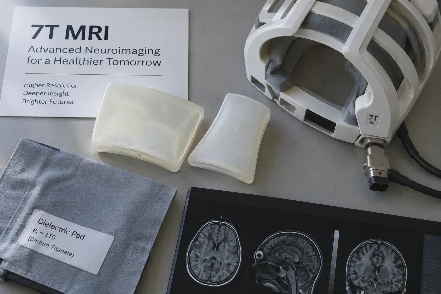
A dielectric pad is a passive device. It contains no electronics, draws no power, and requires no calibration. It consists of a high-permittivity material — typically a suspension of ceramic particles (calcium titanate or barium titanate) in water — housed in a flexible bag placed on or near the subject. The relative permittivity of such suspensions reaches approximately 110, roughly 1.6 to 2.2 times that of biological tissue at 297 MHz.
When the transmit RF field penetrates the pad, the elevated permittivity induces displacement currents within it. These displacement currents generate a secondary magnetic field that adds vectorially to the primary B1+ field produced by the coil. The net effect is a localized augmentation of the transmit field in the region beneath and adjacent to the pad.
The physics is elegant but the deployment is empirical. The magnitude and spatial extent of the secondary field depend on:
- Pad geometry (thickness, footprint, curvature)
- Pad composition (permittivity value, dielectric losses)
- Positioning relative to the anatomy of interest
- Subject-specific tissue distribution and head geometry
A pad placed over the temporal lobes enhances B1+ precisely in the regions where the standing-wave pattern creates signal voids. A pad placed poorly — wrong location, wrong thickness — either has no measurable effect or introduces new inhomogeneity in a region that was previously uniform. There is no universal optimal configuration. Every setup is a local optimization.
Material Composition and Design Parameters
The core challenge in pad design is achieving high permittivity at low loss. Biological tissues already have substantial permittivity at MRI frequencies (50–70 for gray matter at 7T), so the pad material must meaningfully exceed this to be effective. Aqueous suspensions of calcium titanate (CaTiO₃) are the most common choice, yielding relative permittivity values around 110 with acceptable dielectric losses.
Barium titanate (BaTiO₃) suspensions achieve similar permittivity values. The choice between them often comes down to availability, biocompatibility of the encapsulation, and mechanical handling properties rather than electromagnetic performance.
| Parameter | Typical Value | Physical Constraint |
|---|---|---|
| Relative permittivity (εr) | ~110 | Must exceed tissue εr (50–70) to produce a meaningful secondary B1+ field |
| Operating frequency | 297.2 MHz (7T proton) | Larmor frequency sets the wavelength that determines mode pattern |
| Pad thickness | 0.5–2 cm | Thicker pads increase secondary field but reduce subject comfort and may introduce susceptibility effects |
| Dielectric loss tangent | Low, but nonzero | Losses convert RF energy to heat; excessive loss reduces B1+ enhancement and raises SAR |
| Encapsulation | Flexible, RF-transparent bag | Must not introduce susceptibility artifacts or constrain conformability |
Computational tools now exist that use model order reduction and field decomposition to optimize pad parameters — thickness, composition, position — for a target region of interest. These tools yield solutions in minutes rather than hours per target field, a dramatic improvement over purely trial-and-error positioning. But the output is only as good as the anatomical model input. Subject-specific optimization remains difficult in practice because the per-subject EM model must capture the geometry and dielectric distribution that actually drive the standing-wave pattern.
Measurable Effects on 7T Neuroimaging
The evidence base for dielectric pads at 7T is specific and quantitative. The pads demonstrably improve B1+ uniformity in targeted regions, with downstream effects on image quality and quantitative accuracy. The magnitude of improvement varies by sequence, anatomy, and pad configuration.
Where the gains are most consistent:
Temporal lobe coverage. The temporal lobes are the canonical failure mode for 7T transmit fields. Pads placed laterally over the temporal bones produce the most reproducible B1+ augmentation. For functional MRI and spectroscopy targeting the hippocampus and surrounding cortex, this is not a convenience — it is often the difference between usable data and discarded data.
Quantitative neuroimaging. Advanced techniques such as NOEMTR (Nuclear Overhauser Effect magnetization transfer ratio) and gluCEST (glutamate chemical exchange saturation transfer) are exquisitely sensitive to transmit field inhomogeneity. B1+ variations of even 10% propagate into systematic errors in magnetization transfer ratio and chemical exchange saturation transfer maps. Dielectric pads reduce this variability and improve the reproducibility of quantitative metrics across subjects.
Parallel transmit complement. Dielectric pads do not replace pTx. They complement it. A well-designed dielectric pad reduces the dynamic range that the parallel transmit system must correct, which relaxes the constraints on RF pulse design and reduces peak local SAR. This is the practical integration point — passive shimming plus active shimming yields better uniformity than either alone.
Dielectric pads do not eliminate B1+ inhomogeneity at 7T. They reduce it in targeted regions, shifting the residual problem into a range that active shimming and sequence-level corrections can manage.
What they do not do:
- Uniformly correct B1+ across the entire brain without subject-specific repositioning
- Eliminate the need for parallel transmit in applications requiring whole-brain coverage
- Function identically across subjects with different head geometries and tissue distributions
SAR Implications and Safety Considerations
Every element introduced into the RF environment of a 7T scanner alters the specific absorption rate (SAR) distribution. Dielectric pads are no exception. By reshaping the B1+ field, they also reshape the local electric field (E-field), and local SAR is proportional to tissue conductivity multiplied by the squared magnitude of the E-field, divided by tissue density.
The direction of SAR change is not always favorable. In some configurations, the same mechanism that enhances B1+ in the target region also concentrates E-field energy in nearby tissue, increasing peak local SAR. In other configurations, the pad redistributes energy more uniformly and reduces peak SAR. The outcome depends on pad position, composition, and the transmit mode of the coil.
This is not a reason to avoid dielectric pads. It is a reason to measure and model their SAR impact under the specific conditions of your protocol. Modern 7T systems with online SAR monitoring and subject-specific SAR modeling can accommodate this, but the operator must be aware that the pad is part of the electromagnetic environment, not an inert accessory.
At present, no universal standard defines acceptable SAR modification by dielectric pads across all commercial 7T platforms and all sequence types. The operator bears responsibility for verifying that the combined RF environment — coil, pad, subject, sequence — remains within regulatory limits. The IEC 60601-2-33 standard sets the boundary, but the pad's contribution to local SAR must be assessed in context.
Practical Deployment: Where Pads Fail
The most common failure mode for dielectric pads is not electromagnetic. It is mechanical. A pad that shifts between acquisitions — due to subject movement, inadequate fixation, or poor conformability — introduces run-to-run variability that is invisible in the images but destructive to quantitative analysis. A B1+ map acquired with the pad in one position does not describe the B1+ field when the pad has moved a few millimeters.
Fixation matters. Adhesive attachment, foam wedges, or integrated head-coil padding that incorporates the dielectric material are all preferable to a bag simply resting on the subject's head.
The second failure mode is subject variability. A pad optimized for a subject with a particular head size and tissue composition will perform differently on another subject. At 7T, the B1+ pattern is sensitive to individual anatomy in ways that are much less significant at 3T. The same pad and positioning protocol can yield markedly different B1+ enhancements across subjects — sometimes by a factor of two or more between the best- and worst-responding individuals — because the secondary field generated by the pad interacts with the subject's own standing-wave mode structure. For group-level quantitative studies, this inter-subject variability must be characterized through per-subject B1+ mapping and, where possible, controlled.
The third failure mode is neglecting to update the B1+ calibration after pad deployment. Many 7T protocols include a prescan B1+ map used to correct for transmit field variations during reconstruction. If the pad changes the B1+ field but the calibration does not reflect this, the correction applies the wrong adjustment. The solution is simple — rerun B1+ calibration with the pad in place — but it requires awareness and protocol discipline.
What Dielectric Pads Cost You
The direct cost is trivial: dielectric pads are inexpensive to fabricate and require no infrastructure beyond a 7T scanner. The indirect costs are subtler.
Time. Pad positioning adds a few minutes to setup. B1+ recalibration adds more. For a 45-minute neuroimaging protocol, this is modest. For a high-throughput clinical scan list, it accumulates.
Compatibility. Pads interact with receive arrays, RF shields, and patient positioning hardware. A pad that enhances the temporal lobes may also modify the receive sensitivity profile of the surface coils in that region. For quantitative techniques where receive profile correction matters, this must be accounted for.
Standardization. If your center publishes quantitative 7T data and your collaborator does not use pads (or uses different pads), your measurements are not directly comparable. B1+ is a confound in every quantitative MRI metric. Dielectric pads reduce one source of B1+ variability while potentially introducing another source of inter-site variability. The field has not yet converged on standard pad specifications.
Current State of the Art
The trajectory is clear. Computational pad design tools have matured from hours-long simulations to minute-scale optimization, making subject-specific pad tuning feasible in a research setting. High-permittivity materials with well-characterized dielectric properties at 297 MHz are commercially available. Integration of dielectric pad logic into parallel transmit pulse design algorithms is an active area of work — treating the pad and the pTx system as a single coupled electromagnetic optimization problem rather than two independent corrections.
What has not changed is the fundamental physics. At 7T, the wavelength in tissue is shorter than the anatomy. Dielectric pads exploit high-permittivity materials to locally reshape the transmit field through displacement-current-driven secondary magnetic fields. They are effective, inexpensive, and limited. They reduce B1+ inhomogeneity in targeted regions — most reliably in the temporal lobes — but they do not eliminate it. They shift residual inhomogeneity into a range that active shimming can handle. They alter SAR distributions in ways that require case-by-case verification.
A dielectric pad is a targeted electromagnetic patch, not a global correction. Treating it as a universal fix for 7T B1+ inhomogeneity is a misunderstanding of the physics.
The scanner remains a wave-interference machine. The pad is a material intervention that reshapes one node of the standing-wave pattern. For the acquisition physicist, this is the useful framing: dielectric pads are one layer in a multi-layer B1+ management strategy that also includes coil design, parallel transmit, pulse sequence optimization, and post-processing correction. No single layer is sufficient. The pad layer is among the simplest and most cost-effective. Deploy it with precision. Measure its effects. Account for its limitations.