On the first routine simultaneous acquisition, the T1-weighted image appears with parallel bright bands crossing the anatomy. The PET data look plausible. The MR image does not.
The first instinct is often to blame motion, sequence settings, or an unlucky reconstruction. But when the pattern persists across repeated acquisitions and changes with the PET insert enabled or disabled, the problem is more fundamental: the two systems are talking over each other.
This is the central engineering risk in simultaneous PET-MRI. PET detector electronics operate inside the MRI bore, close to the receive chain that is trying to detect extremely weak MR signals. If those electronics are inadequately shielded, the MR noise floor rises, zipper artifacts appear, and the resulting loss of image quality can turn a technically successful acquisition into a clinically marginal one.
A hybrid scanner is two physics experiments sharing one hostile room. The whole engineering exercise is teaching them to politely ignore each other.
The Physics of Mutual Interference in Hybrid PET-MRI Systems
PET and MRI were never designed to cohabit. MRI fills the bore with a strong static magnetic field, rapidly switching gradients, and high-power RF transmit pulses at the Larmor frequency. PET brings a ring of scintillation detectors, photosensors, front-end electronics, digitizers, clock oscillators, power converters, and data links into the same space.
Every one of those components has an electromagnetic signature.
The MRI transmit coil deposits substantial RF energy into the patient and surrounding hardware during excitation. The receive coil then has to recover a comparatively tiny signal from the resulting magnetization. PET electronics, meanwhile, contain fast digital transitions and periodic clock signals that can radiate at their fundamental frequencies and harmonics. Some of those emissions can fall inside, or close enough to, the MR receiver bandwidth to be interpreted as signal.
The interference is bidirectional:
- MRI transmit pulses can disturb PET count rates or saturate sensitive detector electronics during parts of the acquisition.
- Gradient switching can induce voltages in PET cabling, detector assemblies, and conductive structures.
- PET clocks, power supplies, and digital data paths can raise the MR noise floor.
- Imperfect shielding or grounding can create narrowband interference that appears as lines or bands in the reconstructed MR image.
- Conductive PET structures can alter the RF field distribution, affecting transmit efficiency and B1 homogeneity.
The mechanism is unglamorous. RF energy does not respect the dotted line on a system block diagram. A clock line on a PET digitizer board radiates at its harmonics; one of those harmonics lands inside the MR receiver bandwidth, and the receiver dutifully reconstructs it as a structured artifact. If the source is periodic, the artifact is often periodic. If the source is distributed around a detector ring, the pattern can span a large part of the image.
That is how a component that looks electrically minor on a PET schematic becomes a visible defect in an MR image.
The problem is not limited to the detector ring itself. Power distribution, cooling hardware, cable penetrations, optical conversion boards, and mechanical interfaces can all provide coupling paths. A shielding design that works on a bench may behave differently once installed in the bore, where the geometry of the scanner, patient table, gradient assembly, and RF coils becomes part of the electromagnetic system.
This is why simultaneous PET-MRI is an engineering achievement, not merely a sales configuration. Two otherwise incompatible detector technologies were forced into the same room and told to behave.
Quantifying Signal Degradation: From SNR Loss to B1 Field Distortion
The numbers are not abstract. They are the difference between a clinical scan and a re-scan.
A PET insert placed inside the MRI bore can attenuate the transmit B1 field and disturb its spatial uniformity. In the figures used for this type of integration problem, the insert has been associated with approximately 3.2 dB of B1 amplitude loss and an 8.4% reduction in field homogeneity. Separately, inadequately shielded PET electronics can raise the MR background noise level by roughly 15%, with reported MR image SNR losses in the range of 3.1 to 4.2 dB.
Those values should not be treated as universal performance specifications for every commercial system. They are useful as engineering warning signs: the insert, shielding, coil design, and sequence calibration cannot be evaluated independently.
A simplified comparison looks like this:
| Parameter | Poorly integrated PET insert | Properly integrated hybrid |
|---|---|---|
| MR background noise floor | Elevated by electronic interference | Controlled near the MRI baseline |
| MR image SNR | Measurable degradation, potentially several dB | Kept close to the standalone MR reference |
| MR transmit B1 amplitude | Reduced by conductive and geometric loading | Compensated through coil and sequence design |
| B1 field homogeneity | Distorted by the insert and surrounding structures | Managed through shimming and RF redesign |
| PET count rate during MR transmit | Variable suppression or instability | Stabilized through detector and front-end integration |
| Artifact appearance | Zipper bands, narrow lines, or structured noise | No clinically relevant RF pattern |
The dB figures are deceptively polite. A 3 dB SNR loss is not a cosmetic difference; it represents a substantial reduction in signal relative to noise. A further loss can make small lesions, subtle cortical abnormalities, or low-contrast structures less conspicuous. The practical effect depends on the sequence, anatomy, field strength, coil, reconstruction, and clinical question, but the direction is clear: the system has less margin.
B1 distortion creates a different class of problem. If the transmit field is weaker or less uniform than expected, the nominal flip angle is no longer the actual flip angle everywhere in the volume. That changes contrast, affects fat suppression, and can produce spatially variable signal intensity. The image may not show a dramatic zipper artifact at all. It may simply look inconsistent, with areas of poor suppression or unexpected shading that are easy to attribute to patient size or coil loading.
Why SNR and B1 problems can hide in routine workflow
A scanner can remain technically operational while its performance has degraded. The console may accept the protocol, the PET detector may continue to produce counts, and the MR reconstruction may complete without an error message. None of those facts proves that the hybrid system is performing as it did at acceptance.
Several effects make the problem easy to miss:
- A noisy sequence may be mistaken for a naturally low-SNR protocol.
- A B1 problem may appear only with certain body regions, patient sizes, or receive coils.
- A zipper artifact may be intermittent and absent during a quick service check.
- Automatic shimming and intensity correction can conceal some field nonuniformity while leaving other defects untouched.
- Technologists may repeat the sequence without changing the PET operating state, allowing the artifact to return unchanged.
The correct comparison is not with memory. It is with a controlled reference: the same phantom, sequence, shim conditions, coil configuration, and PET operating state, acquired with the insert active and inactive.
The Zipper Artifact: Identifying RF Noise Sources in the Bore
The diagnostic giveaway is often the artifact itself. RF electromagnetic interference inside an MRI scanner produces characteristic zipper artifacts: parallel bright lines or bands across the image, usually aligned with the readout or phase-encode direction depending on how the noise couples into the receive chain.
They look almost intentional, which is what makes them dangerous. A narrowband source can create a crisp line. A broader or unstable source can produce a fuzzy band or a collection of repeated stripes. The artifact may appear in one sequence and not another because the receiver bandwidth, sampling scheme, center frequency, or coil configuration changes.
A tired reader can plausibly mistake a zipper band for a flow artifact, motion ghost, or even a focal lesion if the orientation is unlucky. The first job is therefore not to identify the exact circuit. It is to establish whether the pattern follows the patient or follows the hardware.
Three telltales point toward RF crosstalk rather than patient motion or gradient instability:
1. The artifact remains stationary across repeated phantom acquisitions.
Patient motion changes anatomy and produces ghosts related to the motion cycle. A hardware-generated RF line tends to remain fixed in image space or recur at a characteristic position.
2. The artifact correlates with the PET insert state.
Compare acquisitions with the PET detectors powered, placed in standby, and fully disabled according to the manufacturer’s procedure. If the band appears only when a particular subsystem is active, the console log and acquisition timing become useful evidence.
3. The artifact changes when PET high voltage or front-end electronics are disabled.
A controlled change in detector operating state can distinguish a source inside the PET ring from an external room source. This should be performed within approved service and safety procedures, not as an improvised experiment during a patient examination.
Other clues matter as well. If the artifact frequency shifts when a clock, power converter, or data link changes state, the source may be a narrowband digital oscillator. If the pattern appears only during specific gradient-intensive sequences, inductive coupling or cable routing deserves attention. If it persists with the PET insert completely inactive, the cause may be elsewhere in the scanner room: a monitor, intercom, physiological sensor, cable penetration, lighting system, or damaged room shielding.
A zipper artifact is not the diagnosis. It is the system telling you that the diagnosis has to happen at the hardware level.
A practical troubleshooting sequence
A useful investigation proceeds from the least invasive comparison to the most detailed service measurement:
- Repeat the sequence on a uniform phantom, keeping the coil, shim, center frequency, bandwidth, and reconstruction settings constant.
- Acquire the same sequence with the PET subsystem in the approved inactive state.
- Record whether the artifact changes with PET high voltage, detector clocks, cooling systems, and optical data links.
- Check whether the artifact position changes with receiver channel selection or coil configuration.
- Compare the observed pattern with prior acceptance images rather than with a generic image-quality target.
- Inspect service logs for changes in detector firmware, clocking, power supplies, grounding, or recent maintenance.
- Only then move to electromagnetic probing, cable-by-cable isolation, and physical inspection of the shielding enclosure.
This order matters. Replacing a detector board before proving that the detector electronics are the source is an expensive way to turn an intermittent artifact into a permanent troubleshooting project.
Engineering Solutions: Faraday Shielding and SiPM Integration
The fix is layered, and none of it is glamorous.
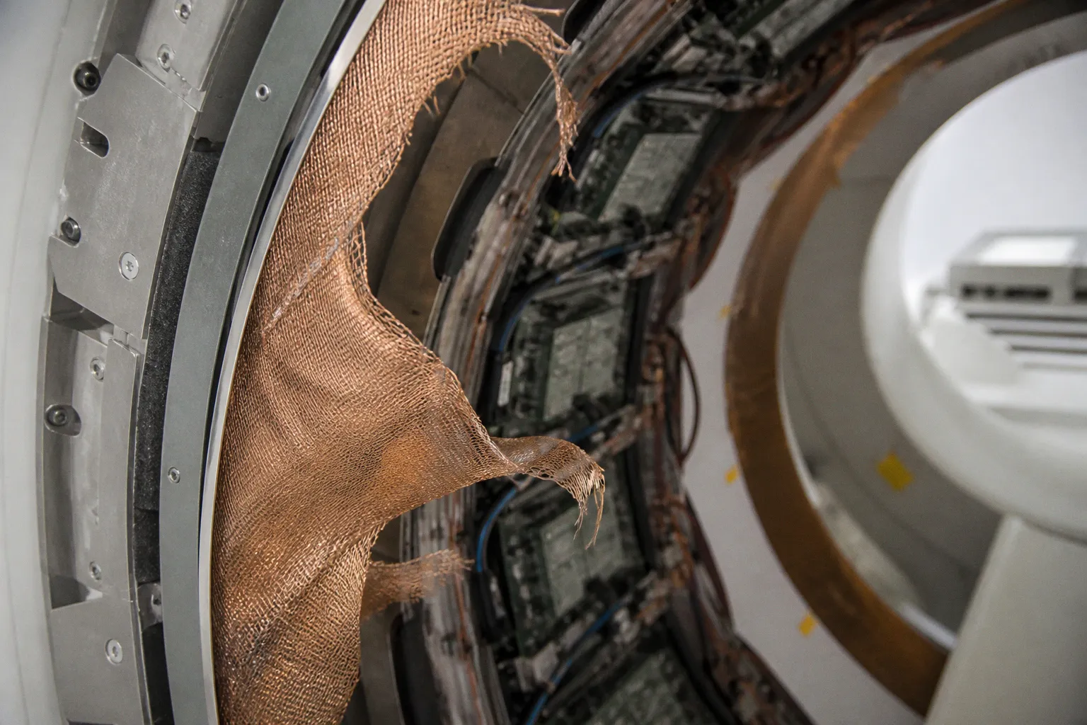
The first line of defense is RF shielding around the PET detector electronics. A copper Faraday enclosure can attenuate emissions from the front-end electronics while preventing the MR transmit field from coupling directly into sensitive digital circuitry. In the integration figures used for this class of design, a copper layer around 17.5 µm is cited as a practical shielding thickness for controlling emissions near the Larmor frequency.
Thickness alone is not the whole design. The enclosure must be continuous enough to prevent leaks at seams, fasteners, access panels, ventilation paths, and cable exits. A tiny discontinuity can act as a slot antenna. A poorly filtered penetration can bypass an otherwise effective shield. The enclosure also needs a controlled grounding strategy; adding random conductive connections after installation can create new loops and new coupling paths.
The bandwidth target matters too. Shielding is not evaluated against all frequencies equally. The relevant question is whether the enclosure suppresses emissions that fall inside the MRI receiver’s sensitive range, as well as harmonics and transient components that can mix into that range. A shield that looks effective during a broad sweep may still fail at a narrow frequency where a PET clock is particularly energetic.
There is a trade-off. More conductive material inside the bore can alter the RF field and increase loading. The shield that protects the MR receiver may also reduce transmit efficiency, disturb B1 homogeneity, or create local field perturbations. That is why shielding cannot be treated as an afterthought added around an already finished PET ring.
SiPMs instead of photomultiplier tubes
The second line of defense is the photosensor itself. Traditional photomultiplier tubes are not compatible with the high static magnetic field of an MRI system. Their electron trajectories are affected by the field, and even modest fringe-field exposure can compromise gain and quantitation.
Avalanche photodiodes offered a practical alternative for early PET-MRI designs. Silicon photomultipliers have become increasingly important because they are compact, fast, and inherently tolerant of strong magnetic fields. They also support detector geometries that can be integrated more closely with the MRI hardware.
That does not make a SiPM-based detector automatically quiet. The sensor may tolerate the static field while its bias circuitry, amplifiers, digitizers, and clock distribution still radiate or respond to gradient switching. The front-end layout remains decisive. Short current paths, controlled impedance, filtering, careful power regulation, and physical separation between noisy digital sections and sensitive analog paths all matter.
The engineering question is not simply whether the detector works in a magnetic field. It is whether the complete detector module works without injecting interference into the MR receive chain or accepting unacceptable interference from the MRI system.
Moving data as light
The third line of defense is signal transport. Once the detectors are shielded, the data still have to leave the bore. Electrical cables can become antennas, especially when they run through changing gradient fields or cross shielding boundaries without proper filtering.
Electro-optical conversion at or near the detector head addresses part of this problem. PET signals are converted into light pulses and carried over fiber to a receiver outside the Faraday room or outside the most sensitive region of the scanner. Fiber is not a magic word, but it removes the conductive path that would otherwise carry common-mode noise and RF pickup.
The details remain important:
- The optical transmitter needs a stable, low-noise power supply.
- Any electrical connection that remains inside the bore must be filtered and mechanically controlled.
- Fiber routing must avoid unnecessary loops and maintain the specified bend radius.
- The transition between shielded and unshielded sections must be designed rather than improvised.
- Timing stability must be preserved so that optical isolation does not compromise PET coincidence processing.
- Cooling systems must not create an unfiltered path through the RF enclosure.
This is the part of integration that rarely makes it into the marketing deck, and it is often the part that determines whether the hybrid system works reliably on an ordinary Tuesday afternoon.
Mature PET-MRI engineering is not glamorous. It is a copper wall, a silicon photomultiplier, and a fiber-optic cable that nobody talks about at user meetings.
Acceptance Testing and PET-MRI Shielding Degradation
Most of the friction never reaches the radiologist. By the time a zippered image lands on the diagnostic workstation, the chain of decisions that produced it was made months earlier by an integration engineer, a vendor applications specialist, and a physicist responsible for acceptance testing.
That is the operational risk. A system can pass installation and still develop a problem later. Shielding seams can be disturbed during service. Cable assemblies can be replaced with a different part. A power supply can begin radiating outside its previous profile. Software or firmware changes can alter clocking and synchronization. A grounding connection can loosen. None of these failures necessarily produces a scanner error.
A useful baseline check should be performed at acceptance and repeated according to the site’s quality-assurance program:
- Image a uniform phantom with the PET ring in its normal operating state.
- Repeat the acquisition with the PET subsystem in the approved inactive state.
- Use the same MR sequence, coil, shim, receiver bandwidth, center frequency, and reconstruction settings.
- Compare SNR, visible artifacts, intensity uniformity, and any change in the B1-sensitive behavior of the sequence.
- Save the raw or minimally processed data when the system allows it, so that later comparisons are not limited to screenshots.
- Record the exact PET operating condition, including detector voltage, cooling state, clocks, and synchronization mode.
- Keep the acceptance images accessible to service engineers and the clinical physics team.
The difference between active and inactive conditions should be small and stable. A growing gap is more informative than a single threshold. If the site’s baseline showed less than approximately 1 dB of difference and a later test shows a substantially larger change, the question is not whether the image still looks acceptable to the eye. The question is what changed in the system.
A phantom test can also reveal B1-related degradation that a simple visual artifact check misses. Compare uniformity across the same volume, inspect fat-suppressed sequences, and look for spatially consistent shading that follows the insert geometry rather than the phantom. The PET ring may be quiet in the narrowband sense while still changing RF loading.
What should be in the service conversation
When an artifact is reported, the useful evidence is specific:
- Which sequence produced it?
- Was it present on a phantom as well as on a patient?
- Did it appear in all receiver channels or only selected channels?
- Was the PET subsystem acquiring, idle, or powered down?
- Did the artifact move when the receiver bandwidth changed?
- Did it change with detector high voltage or cooling state?
- Is it new relative to acceptance images?
- Were any detector, power, cable, software, or shielding components serviced recently?
“Bad image quality” is a poor service description. “Narrowband bands appear only when the PET front end is enabled, remain fixed on a uniform phantom, and disappear when the detector high voltage is disabled” gives the engineer a starting point.
The goal is not to blame the technologist for reacquiring the sequence. Reacquisition is reasonable when the cause is uncertain. The failure is allowing repeated reacquisition to become the quality-assurance strategy.
Optimizing PET-MRI Hardware for Simultaneous Data Acquisition
Hybrid PET-MRI scanners cost more, sit heavier, draw more power, and demand more shielding than either modality alone. None of that is controversial. The decision is whether simultaneous acquisition produces information that sequential imaging cannot provide with acceptable loss of accuracy, workflow, or patient tolerance.
Simultaneous acquisition is valuable when temporal alignment is part of the clinical or research question. Motion correction, attenuation correction, dynamic tracer studies, and protocols requiring closely registered PET and MR information can benefit from collecting both datasets in the same physiological state. Pediatric imaging is another case where reducing repositioning and repeated movement can have practical value.
Sequential PET and MRI may be the better engineering choice when the diagnostic question does not depend on simultaneity. Two scanners scheduled back-to-back can avoid some integration complexity, simplify service, and provide more flexibility in replacing or upgrading one modality. The answer depends on workflow, patient population, tracer protocol, MR sequence requirements, and the quality of the available registration and motion-correction pipeline.
The mistake is to treat every hybrid installation as if it belongs to the most demanding use case. Simultaneous PET-MRI is not automatically superior because the data are acquired at the same time. It is superior when the timing relationship changes the clinical interpretation or materially improves the measurement.
For procurement and design teams, the important questions are consequently more detailed than whether the system supports simultaneous acquisition:
- How was MR image quality measured with the PET subsystem active?
- Were artifact tests performed across the sequences the site actually plans to use?
- What are the baseline SNR, uniformity, and B1 measurements?
- How are RF emissions from clocks, power converters, cooling systems, and data links controlled?
- What happens when a shielding panel or detector module is serviced?
- Does the service agreement include repeat RF and image-quality testing after relevant repairs?
- Are raw-data diagnostics available when an artifact appears?
- Can the site compare current performance with original acceptance data?
- Which PET operating states are compatible with each MR sequence?
A vendor demonstration can show that the scanner produces a clean image under selected conditions. Acceptance testing has to establish that the system remains clean under the site’s real protocols.
The bore is not quiet because the brochure says it is. It is quiet because the detector electronics, shields, optical links, grounding, coil design, and service procedures all continue to behave as designed.
A hybrid scanner is a tool: a very expensive, very RF-hostile tool that places two sensitive measurement systems inside one constrained geometry. Use it where the physics demands simultaneity. Use sequential imaging where the diagnostic question does not. And when a zipper pattern appears, treat it as a hardware symptom, not as an invitation to keep pressing the repeat button.