That range is not a marketing specification. It is a warning against treating all MRI SNR claims as interchangeable.
The strongest gains appear where conventional receive coils are physically inefficient: low-field MRI, low-gamma nuclei, small anatomical targets, and multi-nuclei systems such as sodium imaging. Proton imaging at 1.5 T or 3 T is a more constrained case. The patient remains part of the noise budget. Cooling the conductor does not remove sample noise. It reduces one term in the receiver chain.
That distinction determines whether superconducting radiofrequency coils are clinically useful or merely technically impressive.
The physics of thermal noise reduction in superconducting receivers
The receiver coil is not a passive loop waiting for signal. It is a resistive electrical system coupled to a resonant circuit, a preamplifier, a matching network, and the lossy electromagnetic environment of the patient. Every resistive element generates thermal noise. The receiver must separate the weak induced MR voltage from that background.
For a conventional copper coil, conductor resistance is finite. The resistive loss rises with frequency because of skin effect and proximity effect. Current crowds toward the conductor surface. Adjacent conductors interact. Dense phased-array layouts increase coupling and complicate decoupling. The result is not a single noise source but a network of losses that degrades effective sensitivity.
A superconducting coil changes the balance.
High temperature superconducting materials such as YBCO and BSCCO operate at temperatures near or above a superconducting transition threshold of approximately 90 K. In liquid-nitrogen-compatible operation, the practical reference point is 77 K, or about −196 °C. At that temperature, electrical resistance approaches zero compared with ordinary copper conductors.
The word “approaches” matters. The coil is not an ideal mathematical conductor. It still has dielectric losses, coupling losses, radiation losses, contact losses, and losses associated with the surrounding cryostat and tuning hardware. But the resistive contribution from the superconducting trace can fall sharply. When that contribution is significant in the total noise budget, the measured SNR rises.
A useful simplified relationship is:
\[
\mathrm{SNR} \propto \frac{V_\mathrm{signal}}{\sqrt{R_\mathrm{coil}+R_\mathrm{sample}+R_\mathrm{electronics}}}
\]
This is not a complete MRI noise model. It is sufficient to identify the engineering constraint. Reducing \(R_\mathrm{coil}\) yields a substantial benefit only when \(R_\mathrm{coil}\) is a meaningful fraction of the denominator.
At high field and with a large human subject, sample noise can dominate. The body absorbs RF energy and contributes its own thermal noise. In that regime, reducing coil resistance produces diminishing returns. At low field, or when imaging nuclei with weak MR sensitivity, the coil and electronics can occupy a larger share of the noise budget. Cooling becomes more valuable.
Superconductivity does not create signal. It removes part of the noise that prevents the receiver from using the signal already present.
This is why high temperature superconducting RF coils for MRI should not be described as universal SNR multipliers. A reported 500% improvement in a sodium or other multi-nuclei application does not translate directly to a whole-body proton protocol at 3 T. The electromagnetic regime is different. The noise partition is different. The coil geometry is different.
Why low-field systems benefit disproportionately
Low-field MRI systems operate with lower Larmor frequencies and weaker equilibrium magnetization. The received signal falls. Conventional copper coils do not become noiseless as the field decreases. Their thermal noise remains governed by resistance, bandwidth, temperature, and circuit design.
At 0.2 T, published work has reported SNR gains of approximately 2.8-fold using superconducting receive technology. The significance is not the multiplier alone. It is the operating point. A gain at low field can change acquisition feasibility:
- A sequence that previously required long averaging may tolerate fewer repetitions.
- A small surface coil may cover a useful target without sacrificing detectability.
- A low-field platform may recover contrast or resolution otherwise lost to insufficient signal.
- Non-proton imaging may become less dominated by receiver noise.
The gain is not free. Cryogenic hardware introduces mechanical, thermal, and electromagnetic constraints. But in low-field systems the trade can be favorable because the receiver is often the limiting component rather than the patient.
Material science: YBCO and BSCCO in modern RF coil design
The two material families most associated with HTS RF coils are YBCO, or yttrium barium copper oxide, and BSCCO, or bismuth strontium calcium copper oxide. Both belong to the high-temperature superconducting class. Both can operate near liquid nitrogen temperatures. Neither behaves like an ideal bulk conductor under realistic MRI excitation.
The material is typically formed as a thin superconducting layer on a substrate. Geometry becomes as important as composition. The RF current distribution, critical current density, field orientation, substrate dielectric properties, and defects in the film all affect performance.
YBCO
YBCO is attractive for high-performance RF applications because it can support high current densities and maintain superconducting behavior at temperatures above 77 K, depending on the formulation and operating margin. Thin-film fabrication enables compact resonators and surface coil structures.
The limitation is field sensitivity. The superconducting state tolerates only a finite combination of RF current, static magnetic field, gradient-induced fields, and local geometric concentration. Sharp corners, discontinuities, and coupling regions can produce current crowding. Local regions may approach critical conditions before the average coil appears stressed.
That behavior constrains coil layout. A design optimized only for unloaded quality factor can fail once the patient, transmit field, and gradient environment are introduced.
BSCCO
BSCCO materials have also supported HTS RF coil development, particularly in conductor forms suitable for cryogenic RF structures. Their implementation depends heavily on tape architecture, substrate construction, interfacial losses, and mechanical handling.
The practical question is not which acronym wins. It is whether the complete coil assembly maintains low loss under the intended pulse sequence. A material with favorable transition temperature is not automatically a superior MRI receiver. The resonator must preserve tuning stability, tolerate RF loading, and remain compatible with preamplifier decoupling.
MgB₂ and conventional NbTi
Magnesium diboride, or MgB₂, has a superconducting transition temperature near 39 K. That is substantially higher than traditional niobium-titanium, with a transition temperature near 9.4 K, but lower than YBCO and BSCCO. The cooling burden changes accordingly.
This distinction is important because “superconducting” is not a single hardware category. Main magnets, gradient systems, and RF receive coils face different requirements. NbTi is established in superconducting magnet technology, where the static field and mechanical forces are dominant design concerns. HTS receive coils operate as localized resonant RF structures. Their required temperature, geometry, field exposure, and failure modes differ.
A concise comparison:
| Material or conductor | Approximate superconducting transition | Cooling implication | MRI RF relevance |
|---|---|---|---|
| YBCO | Near or above 90 K | Compatible with liquid nitrogen-class cooling and cryocooler architectures | Strong candidate for low-noise RF receive structures |
| BSCCO | Near or above 90 K | Similar high-temperature operating strategy | Used in superconducting RF coil development; geometry and losses remain decisive |
| MgB₂ | Approximately 39 K | Requires colder operation than YBCO or BSCCO | Potentially useful where lower-temperature performance is acceptable |
| NbTi | Approximately 9.4 K | Requires substantially colder cryogenic conditions | Established in superconducting magnet systems; less convenient for localized RF receive coils |
The correct comparison is therefore not transition temperature alone. It is total system performance:
- unloaded and loaded quality factor;
- coil-to-sample noise ratio;
- tuning drift during cooling and patient loading;
- RF power handling;
- coupling between array elements;
- cryostat distance from anatomy;
- compatibility with the scanner’s preamplifier architecture.
A superconducting coil placed too far from the subject can surrender much of its theoretical advantage. Sensitivity is geometric. The field of view, conductor placement, and filling factor still constrain the receive signal.
Cryogen-free cooling and the mechanical cost of low noise
Early superconducting receiver concepts were tightly associated with liquid nitrogen. That approach is thermally effective but operationally inconvenient. It requires handling, replenishment, insulation, venting, and a cryostat designed around a consumable coolant.
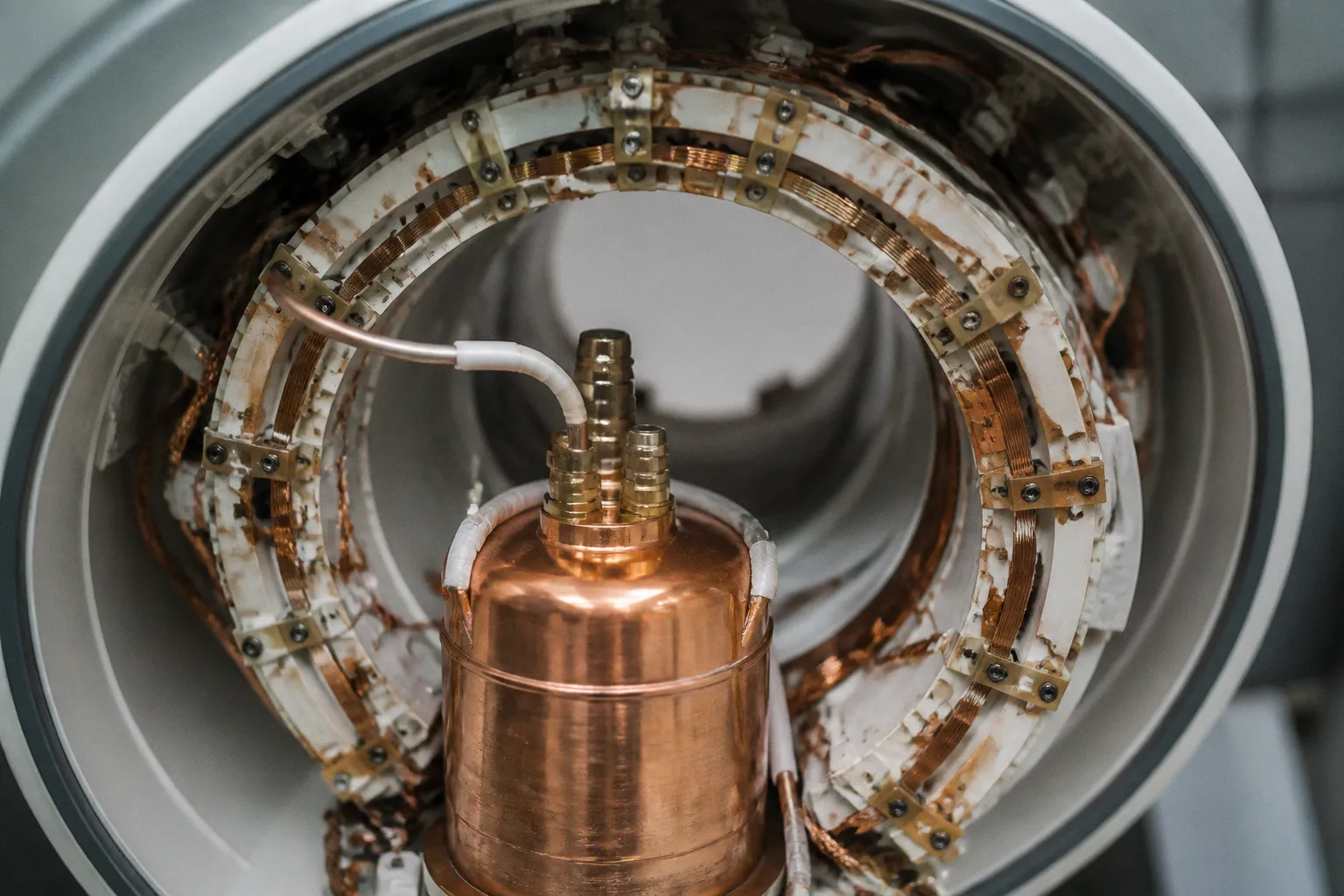
Closed-loop pulse-tube cryocoolers changed the engineering discussion. These systems can maintain cryogenic temperatures without routine liquid-nitrogen filling. Cryogen-free designs reduce logistical dependence and make a user-facing HTS coil more plausible in a clinical or research workflow.
They also add hardware.
A pulse-tube cooler introduces vibration. The compressor and cold head transmit mechanical disturbances through the assembly unless isolated. In MRI, vibration is not a cosmetic defect. It can modulate coil position, alter coupling, generate microphonic interference, and interact with motion-sensitive acquisitions. The effect depends on mechanical coupling and sequence timing, but the risk is structural.
The cryocooler also produces heat at the rejection stage. That heat must be removed without compromising the scanner room environment or destabilizing the coil temperature. Thermal paths must be designed around the RF shield, support frame, cable routing, and patient interface.
The cryostat itself can degrade performance. A thick or poorly selected window increases the distance between coil and anatomy. A conductive structure can support unwanted eddy currents. Dielectric materials can introduce loss and alter the resonant frequency. Every layer between the superconducting element and the patient is part of the RF design.
A cryogen-free HTS assembly must therefore satisfy several conflicting requirements:
1. Maintain a stable operating temperature. The coil needs margin below its transition threshold. Temperature excursions increase surface resistance and reduce performance.
2. Suppress vibration transmission. The cooling system must not turn a low-noise receiver into a mechanical noise source.
3. Keep the coil close to the anatomy. Increased spacing reduces coupling to the target and can erase the expected SNR advantage.
4. Control electromagnetic interaction. The cryostat, thermal straps, shields, and wiring must not create new resonances or eddy-current artifacts.
5. Preserve serviceability. A research prototype can tolerate difficult access. A clinical system cannot rely on delicate manual retuning after every thermal cycle.
Pulse-tube cooling improves usability. It does not simplify the system to the level of a copper coil. The complexity moves from coolant management into thermal-mechanical integration.
Diamagnetism, artifacts, and the failure of idealized coil models
HTS materials introduce electromagnetic behavior that standard copper-coil simulations may not capture adequately. Superconducting structures exhibit strong diamagnetic response. The surrounding static and RF fields are perturbed by the material, the substrate, the shielding arrangement, and the resonant current distribution.
The consequence can be image artifact.
A receive coil is expected to detect the signal without significantly distorting the field environment. An HTS coil can violate that assumption if its geometry creates local field perturbations, nonuniform loading, or spatially varying sensitivity patterns that are not handled by the reconstruction pipeline.
The artifact mechanisms are not limited to one effect. They can include:
- local sensitivity nulls or intensity gradients;
- field perturbation near the coil surface;
- resonance shifts caused by patient loading;
- temperature-dependent tuning changes;
- coupling between the coil and conductive shielding;
- unstable behavior under high RF excitation;
- phase errors that complicate multi-channel reconstruction.
The design target is not maximum \(Q\) in isolation. It is predictable loaded behavior.
A high unloaded quality factor can become irrelevant when the patient dominates loading or when the coil’s sensitivity profile is poorly matched to the anatomy. Similarly, an impressive bench SNR measurement may not survive in vivo if the cryostat increases coil-to-sample distance or if decoupling fails under realistic loading.
RF decoupling is a system problem
Transmit/receive decoupling is one of the central engineering challenges for superconducting RF coils. The receive element must remain sensitive to the MR signal while tolerating the transmit field and avoiding destructive interaction with neighboring channels.
Conventional copper arrays use established methods: geometric overlap, capacitive decoupling, preamplifier decoupling, active detuning, and carefully controlled cable traps. HTS arrays can require different implementations because the superconducting element has a different impedance behavior, different current distribution, and different response to strong RF fields.
The receive coil must not become an uncontrolled resonator during transmission. If active detuning is incomplete, transmit power can couple into the receiver. That can produce heating, instability, or damage. If neighboring elements are insufficiently isolated, the array matrix becomes ill-conditioned. Reconstruction then amplifies noise or produces spatial artifacts.
For multi-channel systems, the relevant object is the noise covariance matrix, not a single channel SNR value. Coupled coils generate correlated noise. The reconstruction algorithm must estimate and manage that covariance. A superconducting array that improves individual channel sensitivity but worsens inter-channel correlation may yield less practical benefit than its component-level measurements suggest.
The decisive metric is loaded, reconstructed SNR under the intended sequence—not the quality factor printed on a coil datasheet.
This is where hardware and software meet. Coil sensitivity maps, noise pre-whitening, parallel imaging calibration, and motion correction all depend on stable receiver behavior. A coil that changes tuning with temperature or patient loading contaminates calibration data. The result is not merely a hardware defect. It becomes a reconstruction problem.
Why multi-nuclei imaging exposes the value of HTS hardware
Proton MRI benefits from high abundance and favorable gyromagnetic properties. Other nuclei do not receive that advantage. Sodium, for example, produces weaker signal and often requires specialized coils, nonstandard pulse sequences, and compromises in spatial resolution or acquisition time.
This is the environment where HTS RF coils can produce unusually large gains. The available evidence includes reported SNR improvements from 50% to 500% over copper coils in multi-nuclei applications. The upper end is application-specific. It should not be generalized to every scanner or anatomy.
The mechanism is straightforward. A low-sensitivity nucleus generates a smaller voltage at the receive coil. If coil thermal noise remains substantial, reducing conductor noise produces a larger relative improvement. The same reduction that yields a modest benefit in a proton exam can produce a decisive benefit in sodium imaging.
The practical consequences include more usable signal for:
- metabolic imaging;
- cartilage and musculoskeletal sodium studies;
- brain sodium measurements;
- phosphorus or other non-proton spectroscopy applications;
- low-field research platforms where signal is already constrained.
However, multi-nuclei imaging imposes additional hardware requirements. The coil must resonate at the target frequency. Its tuning network must remain stable at cryogenic temperature. If the design includes multiple nuclei or dual-tuned operation, the resonant modes must be isolated. Harmonic interactions and cable coupling can become dominant failure paths.
Magnetic resonance spectroscopy adds another layer. Spectroscopy is sensitive to frequency stability, phase behavior, linewidth, and contamination from nearby resonances. A superconducting coil that increases amplitude but introduces instability or spatially varying frequency response may not improve the final metabolite quantification.
This is the difference between more signal and better measurement. The latter requires the entire acquisition chain to remain controlled.
HTS coils at ultra-high field: promise constrained by sample noise
The phrase “ultra high field MRI coils” often implies that superconducting receive hardware is an obvious next step. The physical case is less simple.
At ultra-high field, proton signal increases, but RF wavelength shortens inside tissue. B1 inhomogeneity becomes more severe. Specific absorption rate constraints tighten. Dielectric effects become more pronounced. The coil must manage transmit field uniformity, local heating, coupling, and patient loading.
An HTS receive element may reduce coil noise, but it cannot by itself solve transmit-field nonuniformity or SAR constraints. If sample noise dominates, the SNR gain from cooling the conductor may be smaller than expected. If the coil is placed close to the anatomy and designed for a small target, the benefit may remain meaningful. The result depends on geometry and application.
For ultra-high-field systems, the engineering hierarchy is therefore different:
1. establish the transmit field and safety envelope;
2. characterize sample loading and noise dominance;
3. model coil sensitivity and coupling under realistic anatomy;
4. evaluate the cryostat’s effect on distance and field distribution;
5. measure reconstructed performance under the target acceleration and sequence.
A cold coil does not exempt the system from Maxwell’s equations. It still has to produce a usable field pattern inside a lossy, heterogeneous body.
Acquisition speed: SNR is useful only when it changes the protocol
Higher SNR can be exchanged for multiple outcomes. The operator may increase spatial resolution, reduce averaging, shorten echo-train demands, or preserve image quality under faster acquisition. The choice is not automatic.
If SNR improves by a factor \(G\), acquisition time can theoretically fall approximately with the square of that factor for an otherwise equivalent noise-limited measurement. Real protocols rarely achieve the ideal result. Motion, physiological variation, reconstruction penalties, acceleration, relaxation behavior, and sequence-specific losses intervene.
An HTS coil can therefore enable faster MRI, but only if the sequence is limited by receiver noise. If the sequence is limited by motion, SAR, gradient performance, chemical-shift behavior, or preparation time, the additional SNR may not reduce total scan duration.
This point matters for clinical translation. A coil should be evaluated against the protocol bottleneck, not against a generic SNR benchmark.
| Limiting factor | What HTS cooling can improve | What it cannot solve |
|---|---|---|
| Receiver thermal noise | Reduces the coil-resistance contribution and can raise SNR | Does not remove patient sample noise |
| Weak non-proton signal | Improves detectability when coil noise is significant | Does not make low-abundance nuclei behave like protons |
| Long averaging requirement | May reduce repetitions in a noise-limited scan | Does not remove motion or physiological instability |
| High-density array sensitivity | Can improve element sensitivity | Does not automatically solve coupling or covariance problems |
| Low-field image quality | Can recover sensitivity lost to low magnetization | Does not restore high-field contrast mechanisms |
| Cryogenic operation | Lowers conductor noise with suitable materials | Adds vibration, thermal, mechanical, and service complexity |
The system must be benchmarked with the final reconstruction. Raw signal amplitude is not enough. The correct measurement includes loaded SNR, spatial uniformity, temporal stability, artifact rate, and behavior across the full sequence library.
Clinical hardware must tolerate the operating room, not just the physics lab
A laboratory HTS coil can be optimized for one anatomy, one nucleus, one field strength, and one pulse sequence. Clinical hardware must tolerate broader use.
It must survive repeated thermal cycles. It must maintain tuning after handling. It must interface with existing scanner electronics. It must meet MRI safety requirements for conductive structures, cables, fixation hardware, and patient contact surfaces. It must remain predictable when the patient is not positioned exactly as expected.
Safety protocols also become more demanding when cryogenic components are placed near the patient. The design must address cold surfaces, vacuum failure modes, mechanical containment, pressure management, electrical isolation, and emergency procedures. The details depend on the implementation. The general constraint does not: the cryostat is part of the patient-facing medical device.
The receive coil must also tolerate the scanner’s gradient environment. Gradient slew rates induce currents in conductive structures. Those currents can create heating, forces, vibration, and image artifacts. The superconducting trace itself is not the only concern. Shields, supports, cables, and thermal assemblies can become unintended current paths.
A design that performs well in a static phantom may degrade during rapid imaging. Motion correction cannot repair every hardware artifact. It can estimate and compensate for some changes in anatomy or sensitivity. It cannot reliably remove unstable coupling, sequence-dependent coil detuning, or severe field perturbation without compromising the data.
The acquisition engineer’s evaluation hierarchy
A serious evaluation of high temperature superconducting RF coils for MRI should proceed from system physics rather than headline SNR.
The following measurements carry more weight than an isolated percentage gain:
1. Loaded versus unloaded quality factor. The difference reveals how strongly the patient and surrounding structure dominate losses.
2. Coil-to-sample noise ratio. This identifies whether cooling addresses the actual limiting term.
3. Spatial SNR maps. A high central value is not sufficient if the useful field of view contains severe nonuniformity.
4. Noise covariance across channels. This determines whether the array improves reconstructed performance or merely produces larger correlated signals.
5. Tuning stability across temperature and loading. The resonant frequency must remain controlled during cooldown, patient placement, and sequence transitions.
6. Transmit detuning isolation. The receiver must remain protected during RF transmission.
7. Artifact behavior under gradients. The coil assembly must be tested with the intended gradient waveforms, not only in a quiet static condition.
8. Protocol-level acceleration performance. The relevant output is diagnostic or research utility after reconstruction, not bench sensitivity alone.
9. Thermal and mechanical stability. Pulse-tube vibration, heat rejection, and cryostat integrity affect image quality directly.
10. Operational repeatability. A coil that requires expert intervention after every scan is not a practical clinical receiver.
The hierarchy is deliberately unforgiving. HTS hardware has enough complexity to produce excellent numbers in the wrong measurement.
What superconducting RF coils actually change
HTS RF coils do not replace the MRI scanner. They refine one part of its signal-processing chain: the receive interface between the precessing spins and the reconstruction system.
Their strongest value appears where that interface is the bottleneck. Low-field MRI. Specialized nuclei. Small targets. Surface-limited acquisitions. Research systems that cannot simply increase field strength. In those domains, reducing coil thermal noise can yield the sensitivity required to make an acquisition viable.
The engineering challenges remain substantial. YBCO and BSCCO provide practical high-temperature superconducting platforms, but they require cryogenic control. Cryogen-free pulse-tube systems reduce liquid-nitrogen dependence, but add vibration and thermal complexity. Diamagnetism and field perturbation can produce artifacts. RF decoupling becomes more demanding. Patient loading still dominates many proton applications. Sample noise does not disappear.
The correct conclusion is narrow and useful.
Superconducting receiver hardware matters now because it attacks a measurable limitation in MRI acquisition. It is not a universal path to higher SNR. It is a specialized method for lowering receiver noise where receiver noise is actually constraining the examination.
Everything else is specification theater.