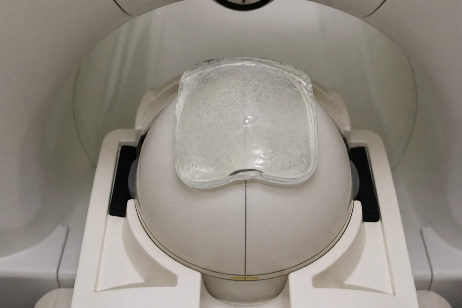
Dielectric Pads at 7T: Placement Rules for Tomorrow’s Scan
The RF wavelength in biological tissue becomes comparable to the dimensions of the head, so the field no longer behaves as though it were evenly distributed across the brain. Constructive and destructive interference can produce bright regions, signal dropouts, and regional contrast changes that are especially troublesome near structures such as the temporal lobes and inner ear.
This is why 7T MRI dielectric pad placement is not a matter of placing a slab of material beside the head and hoping for a smoother image. A pad is a passive RF-shimming device whose geometry, position, thickness, and dielectric properties influence where transmit efficiency is restored. The practical challenge is to connect the visible image artifact to the underlying electromagnetic behavior, then make a controlled adjustment without treating the pad as a universal correction for every patient, coil, or brain region.
At 7T, a dielectric pad is not simply an accessory. It is a local electromagnetic intervention whose effect depends on anatomy, coil geometry, field distribution, and placement precision.
The physics of B1+ inhomogeneity at 7T: why wavelength matters
The central difficulty begins with the RF transmit field, commonly described as B1+. In a lower-field clinical MRI system, the RF wavelength in tissue is generally long relative to the dimensions of the head. The transmit field can therefore appear comparatively uniform, although it is never perfectly so. At 7T, tissue shortens the effective RF wavelength, bringing it closer to the scale of human anatomy.
That shift changes the character of the problem. RF waves travelling through and around the head can interfere with one another, producing local reinforcement in some regions and cancellation in others. The resulting B1+ pattern may vary substantially across the brain, even when the scanner, coil, and nominal acquisition settings remain unchanged.
The visible consequences are familiar to anyone working with ultra-high-field MRI:
- signal dropouts in targeted anatomical regions;
- reduced excitation efficiency, leading to local loss of sensitivity;
- spatially varying contrast that can complicate interpretation;
- apparent asymmetry between corresponding structures;
- regional differences in saturation and tissue signal that may be mistaken for biology rather than transmission physics.
The temporal lobes are a particularly important example because they sit within a region where the 7T transmit field can become uneven, while the structures themselves are relevant to memory, epilepsy, neurodegeneration, and psychiatric research. Inner-ear imaging presents a different but related challenge: the target is small, anatomically constrained, and positioned within a complex RF environment, so a modest local field distortion can have a disproportionate effect on the useful signal.
The difficulty is not merely that 7T produces more artifact. Rather, the artifacts can become entangled with the biological question. A study focused on subtle degradation of hippocampal or temporal-lobe structures may be trying to detect a longitudinal trajectory measured over months or years, while the transmit field introduces a spatial bias that changes the apparent conspicuity of the same anatomy. Consider the implications: if the acquisition is not sufficiently uniform, a difference between time points may reflect hardware positioning or B1+ behavior instead of a change in tissue.
This is one reason dielectric pads remain relevant even as modern 7T systems adopt increasingly sophisticated multi-transmit technology. Parallel transmission and active RF shimming can improve control over the transmit field, but passive shimming remains useful when a specific anatomical region needs additional local correction. The pad does not replace the scanner’s RF system; it modifies the electromagnetic environment in which that system operates.
How titanate suspensions reshape the RF field
High-permittivity dielectric pads work through a mechanism that is easy to describe and less easy to predict intuitively. When the pad is exposed to the RF electric field, displacement currents form within the high-permittivity material. Those currents generate a secondary local RF magnetic field. Depending on the pad’s location and geometry, this secondary field can augment the applied B1+ field in a region that would otherwise suffer from reduced transmit efficiency.
Many dielectric pads use suspensions containing metal titanates, including barium titanate or calcium titanate, mixed into protonated or deuterated water. The titanate component gives the suspension a high relative permittivity. Calcium titanate formulations may have a relative permittivity around 110, while barium titanate suspensions can reach approximately 200 to above 400 depending on concentration, saturation, and pressure conditions.
These values are not interchangeable labels for performance. Relative permittivity is one part of the electromagnetic behavior, and the useful result depends on the complete pad system:
- the dielectric composition and its effective permittivity;
- the physical dimensions of the pad;
- the thickness of the material;
- the distance between the pad and the target anatomy;
- the transmit coil design and operating frequency;
- the patient’s head shape and tissue distribution;
- the target sequence and the desired anatomical coverage.
A calcium titanate MRI pad and a barium titanate suspension may both be described as high-permittivity solutions, but they should not be assumed to produce the same field pattern when placed in the same location. Even two pads made from the same formulation can behave differently if their shape, thickness, or position changes.
The most useful mental model is therefore not that the pad increases signal globally. It is that the pad creates a local field perturbation, and the perturbation can be favorable or unfavorable depending on where it is introduced. The goal is usually to improve B1+ near a target region rather than to maximize signal everywhere in the brain.
Passive shimming versus active RF shimming
Active RF shimming changes the relative amplitude and phase of the transmit channels. It is programmable and can be optimized for a subject or a region of interest, although the optimization process may involve additional calibration and constraints. A dielectric pad, by contrast, has no electronic control once it is positioned. Its effect is passive, repeatable only when the placement itself is repeatable, and strongly linked to the physical relationship between pad and anatomy.
That distinction matters in longitudinal studies. If one participant is scanned with a pad several millimetres closer to the temporal lobe than during the previous visit, the field distribution may not be identical even if the scanner protocol is unchanged. The more subtle the biological endpoint, the more important this procedural consistency becomes.
A pad can be advantageous precisely because it is simple to integrate. Commercial head dielectric pads designed for 7T neuroimaging can be positioned directly on the relevant external anatomy and used without modifying standard MRI pulse sequences. That does not make placement casual. It means the intervention can be incorporated into the existing acquisition workflow without redesigning the sequence each time.
Strategic placement for targeted neuroimaging
There is no universal placement rule that guarantees the same result for every brain region or body type. The appropriate position is target-dependent, and the best geometry is usually established through electromagnetic simulation, prior validation, or a structured local optimization process.
For temporal-lobe imaging, the pad is generally positioned so that its high-permittivity volume is adjacent to the side of the head corresponding to the region where B1+ efficiency needs support. The exact relationship to the temporal lobe, coil housing, and head support matters. A pad that is too far from the scalp may produce a weaker or differently distributed effect; a pad that is pressed into an unintended position may improve one area while creating a new pattern of nonuniformity elsewhere.
The same principle applies to inner-ear imaging, although the anatomical target is smaller and more lateral. A placement that is appropriate for one ear should not automatically be mirrored without considering coil symmetry, patient positioning, and the intended field correction. In bilateral imaging, the objective may be to improve balance between sides rather than to maximize one local signal peak.
The placement process is best understood as a sequence of decisions rather than a single instruction.
1. Define the target region and the failure pattern.
Begin with the anatomy that is affected and the type of impairment seen in the images. A broad temporal-lobe dropout, a focal loss near the ear, and a regional contrast imbalance do not necessarily require the same pad geometry.
2. Relate the artifact to the transmit field.
Signal loss can have more than one cause, including motion, susceptibility, receive sensitivity, and sequence-specific effects. A dielectric pad is intended to address a transmit-field problem, so its use should follow a reasoned assessment that B1+ inhomogeneity is contributing to the observed limitation.
3. Select a validated pad geometry.
High-permittivity pads commonly have thicknesses in the range of 5 to 15 mm, but thickness alone does not determine performance. The outline, surface area, material volume, and location relative to the target all shape the resulting field.
4. Place the pad consistently against the intended external landmark.
The pad should sit in the position for which it was designed or validated, with the same orientation and relationship to the head support wherever possible. Small differences may matter more at 7T than they would at lower field strength.
5. Confirm the result using appropriate image or field-quality checks.
A visually brighter image is not automatically a more reliable image. Evaluate the target region, neighboring anatomy, symmetry, contrast behavior, and any new artifacts introduced by the pad.
6. Document the configuration for repeat imaging.
In a longitudinal protocol, record the pad type, geometry, side, orientation, approximate anatomical landmark, and any relevant positioning details. The aim is not bureaucratic completeness; it is preservation of the measurement trajectory.
The clinical value of passive RF shimming lies less in adding signal than in making the signal interpretable where the biological question actually lives.
Placement and anatomy: why one location cannot serve every question
A pad positioned near the temporal lobes may be useful for a protocol concerned with mesial temporal structures, but that does not mean it will improve the entire brain uniformly. Its local field contribution can extend beyond the intended target, and the resulting pattern may depend on the subject’s anatomy.
This is especially relevant when comparing cohorts with different head shapes, tissue composition, or brain volume. A geometry optimized on a representative simulation may not perform identically across all participants. The practical response is not to abandon passive shimming, but to treat the pad as part of the acquisition configuration and validate its behavior within the population and protocol in which it will be used.
For research groups building a neuroimaging pipeline, this creates an important separation between exploratory and production imaging. During development, the team may examine several validated placements or pad geometries and compare field uniformity, regional signal, and artifact behavior. Once a configuration is selected, production scans should use a stable procedure rather than allowing each operator to make an informal adjustment.
Geometry, thickness, and permittivity: the balancing problem
High-permittivity pads are often discussed as though increasing permittivity or thickness should simply increase the correction effect. The electromagnetic response is more complicated. A pad that is too weak may fail to generate a meaningful secondary field, while a pad that is too strong or poorly shaped may overcorrect one region, shift the field maximum, or create a new nonuniform pattern.
Thicknesses of approximately 5–15 mm are common in practical designs, but this range should be treated as a design context rather than a universal prescription. The appropriate value depends on the target anatomy, the material formulation, the coil, and the intended field manipulation. A 10 mm pad with one suspension is not electromagnetically equivalent to a 10 mm pad with another.
The geometry may be customized around a target region. A broad pad can influence a larger area but may be less selective. A smaller pad may offer more localized correction, while also being more sensitive to positioning error. For temporal-lobe applications, the design question is often whether the pad should support a lateral region broadly or concentrate its effect near a particular structure. For inner-ear work, the balance between local correction and unwanted influence on adjacent anatomy can be even narrower.
A useful comparison is to consider how the main design variables behave in practice:
| Parameter | Lower or smaller configuration | Higher or larger configuration |
|---|---|---|
| Pad thickness | May produce a weaker local perturbation and less correction | May produce a stronger effect but can alter the spatial pattern more substantially |
| Relative permittivity | Can provide limited displacement-current effects | Can generate a more pronounced secondary RF field, though not necessarily a more uniform one |
| Surface area | More localized influence | Broader anatomical coverage with less spatial selectivity |
| Distance from scalp | Often reduces coupling to the intended region | Closer placement generally strengthens the intended interaction, provided the position is validated |
| Geometric precision | More forgiving only if the effect is weak | More consequential because small positional changes may alter the field distribution |
| Clinical interpretation | May leave residual dropout | Can improve target visibility while requiring checks for overcorrection or new artifacts |
This shift allows us to see why the phrase “optimize B1+” can be misleading when used without a target. Optimization is always relative to a goal: uniformity across a lobe, signal preservation in the hippocampal region, bilateral balance, improved visibility of the inner ear, or a more stable quantitative measurement.
Choosing between calcium titanate and barium titanate formulations
The choice between calcium titanate and barium titanate should follow the intended electromagnetic behavior and the validated pad design, not a simple ranking of materials. Calcium titanate suspensions may offer high permittivity in a formulation that is suitable for a particular pad geometry. Barium titanate suspensions can provide still higher effective permittivity, in some conditions reaching approximately 200 to above 400, but the practical result depends on concentration, saturation, pressure, and construction.
The material also has to remain physically stable and manageable in a clinical environment. A formulation that performs well in a laboratory characterization may be less useful if it is difficult to position consistently, prone to leakage, or incompatible with the site’s cleaning workflow. In translational imaging, electromagnetic performance and operational reliability are part of the same design problem.
For that reason, a pad should be treated as a characterized device rather than as an improvised container of high-permittivity liquid. Homemade or unvalidated constructions create uncertainty not only in B1+ correction but also in heating behavior, mechanical integrity, labeling, and cleaning. At 7T, that uncertainty is not a minor inconvenience.
Verification before the scan becomes a study variable
A dielectric pad can make a difficult acquisition more productive, but it does not remove the need for quality assurance. Before introducing a pad into a clinical research sequence, the team should establish what improvement is expected and how it will be recognized.
The most direct checks concern the target anatomy:
- Does the region of signal dropout become more usable?
- Is the correction spatially appropriate, or has the bright region simply moved?
- Does the pad improve the target while degrading neighboring tissue?
- Is the effect consistent across repeated positioning?
- Does the result remain acceptable across different head sizes and anatomical configurations?
- Are contrast and quantitative measures more stable, rather than merely more visually striking?
This is where acquisition expertise and image-analysis expertise meet. A pad may alter regional signal intensity in ways that affect segmentation, cortical thickness estimation, functional MRI sensitivity, or spectroscopy. If an analysis pipeline has been trained or tuned on images without passive shimming, introducing a pad may change the intensity distribution and require renewed validation.
The issue is particularly important for quantitative neuroimaging. A field correction that improves visual uniformity may not automatically preserve the assumptions of a derived measure. Longitudinal work should therefore distinguish between improved anatomical conspicuity and improved measurement reliability. Both may occur, but they should not be presumed to be identical.
Motion adds another layer. A pad that is correctly positioned at the start of a scan may shift relative to the head if the subject moves, and head motion itself can alter the relationship between the pad, the coil, and the target anatomy. Motion correction in the reconstruction or analysis pipeline cannot necessarily recover the electromagnetic conditions that existed before the movement. This is one reason physical stabilization and clear operator documentation remain valuable even in highly automated workflows.
Maintenance and MRI safety protocols for high-permittivity hardware
Cleaning and handling are part of the imaging protocol, not an afterthought. Commercial dielectric pads designed for 7T neuroimaging should be maintained according to their validated instructions. Standard MRI-safe disinfectant wipes, including isopropyl alcohol wipes where compatible with the device, may be used for surface cleaning. The pad should not be autoclaved or fully immersed in liquid.
That restriction is practical as well as hygienic. Immersion can compromise the enclosure or alter the material system, while autoclaving may expose the pad to conditions for which it was not designed. A device that has changed physically may no longer have the electromagnetic properties assumed by the original validation.
Safety review must also account for the interaction between high-permittivity materials and the RF environment. At 7T, local electric and magnetic field behavior can be sensitive to geometry, and specific absorption rate considerations cannot be reduced to a universal placement rule for every custom pad and every scanner. In particular, one should not assume that an untested homemade titanate pad has a predictable safety profile simply because the material itself is used in published or commercial designs.
A robust site procedure should include:
- a defined pad model or formulation with known construction;
- a validated location and orientation for the intended target;
- compatibility review with the scanner, coil, and protocol;
- electromagnetic and safety assessment appropriate to the configuration;
- operator training that emphasizes consistent placement;
- inspection for leakage, deformation, damaged seams, or altered contents;
- cleaning with approved MRI-safe methods rather than autoclaving or liquid immersion;
- documentation of deviations, because a changed pad position can become a meaningful acquisition variable.
The fact that a pad can be used without modifying standard pulse sequences is operationally helpful, but it should not be interpreted as evidence that no validation is necessary. The sequence may remain unchanged while the electromagnetic environment changes. Those are separate facts.
From placement rule to reproducible acquisition
The most useful 7T MRI dielectric pad placement guide is therefore not a universal diagram with one prescribed location. It is a reproducible decision framework tied to the target anatomy, the scanner hardware, the pad’s construction, and the study’s endpoint.
For a protocol focused on the temporal lobes, the team may prioritize local B1+ recovery and stable bilateral imaging. For inner-ear work, the priority may be a more selective correction close to the target with careful monitoring of adjacent structures. For a longitudinal neurodegenerative study, the decisive question may be whether the pad reduces technical variance enough to make subtle biological change easier to measure over time.
The underlying principle remains consistent: start with the failure mode, choose a characterized pad geometry, position it relative to a defined anatomical landmark, and verify the outcome in the images and measurements that matter. The pad should become part of the protocol’s known state, not an informal intervention that varies from one operator or visit to the next.
This approach also keeps expectations realistic. Passive RF shimming can restore transmit efficiency and improve signal uniformity in a selected region, but it does not cure the broader limitations of ultra-high-field MRI. It cannot compensate for every source of artifact, eliminate motion, or guarantee uniformity across all anatomy. Its value is narrower and more concrete: it can make a difficult part of the field more usable when the device is designed and placed with sufficient care.
At 7T, that care is what turns electromagnetic complexity into clinical utility. The important outcome is not a brighter scan in isolation, but a more trustworthy representation of anatomy—one that allows a radiologist, neuroscientist, or image-analysis system to distinguish a real biological difference from the subtle degradation imposed by the acquisition itself.