Contrast becomes position-dependent. A nominally uniform RF pulse can produce a materially non-uniform image.
This is the central hardware problem in ultra-high-field MRI. The static field provides higher potential signal and stronger spectral separation. The RF system then spends that gain correcting its own spatial behavior. Parallel transmit, or pTx, addresses the problem by replacing one global transmit degree of freedom with many independently controlled channels. It does not remove the physics. It gives the system enough control variables to compensate for it.
The physics of 7T: why B1+ inhomogeneity becomes operational
The transmit component of the RF magnetic field is conventionally described as B1+. It determines the local excitation efficiency and therefore the flip angle delivered to tissue. At lower field strengths, the RF wavelength within the body is generally long relative to many anatomical dimensions. The transmit field remains easier to homogenize with a conventional body or volume coil.
At 7T, that assumption degrades.
The wavelength is modified by tissue dielectric properties. Conductivity and permittivity vary across the anatomy. The resulting electromagnetic interaction produces spatial interference in the superposed RF field. Some regions receive constructive excitation. Others experience cancellation. The effect is not a simple global reduction in signal. It is a spatially structured distortion of the excitation profile.
The image consequence is direct:
- Local flip angle deviates from the prescribed value.
- T1-weighted contrast becomes spatially inconsistent.
- Signal voids appear in anatomically relevant regions.
- Quantitative measurements inherit a position-dependent excitation error.
- Receive sensitivity cannot fully correct a transmit-field defect.
That final point is frequently mishandled. Receive-array sensitivity maps can normalize some intensity variation after acquisition. They cannot reconstruct excitation energy that was never delivered to the target tissue. A receive correction may flatten the image. It does not restore the original flip angle or the sequence’s intended contrast mechanism.
At 7T, the scanner therefore becomes a coupled electromagnetic and mathematical system. The static field strength is only one variable. The transmit array geometry, channel phases, channel amplitudes, RF pulse duration, subject anatomy, and local SAR distribution all enter the solution.
At 7T, B1+ shading is not an image-display defect. It is an excitation-field error created before k-space is sampled.
Why the problem is anatomically unstable
The field pattern depends on the subject. Head shape, neck geometry, tissue composition, and loading conditions alter the electromagnetic boundary conditions. A calibration that performs adequately for one subject can produce a different spatial pattern for another. The same scanner. The same coil. A different load.
This creates a distinction between nominal hardware capability and usable protocol performance. A 7T system may have sufficient static field, gradient performance, and receiver bandwidth for a demanding protocol. If the transmit field cannot be controlled over the target anatomy, the protocol remains constrained by spatial excitation.
The problem is also sequence-dependent. A short excitation pulse, a large flip angle, and a broad field of view do not impose the same RF burden. Slice-selective excitation adds spatial constraints. Multiband or rapid acquisition strategies can increase the demand on RF pulse design and SAR management. A pTx implementation must therefore be evaluated as part of a complete sequence, not as an isolated coil specification.
Multi-channel pTx arrays: adding control to the transmit field
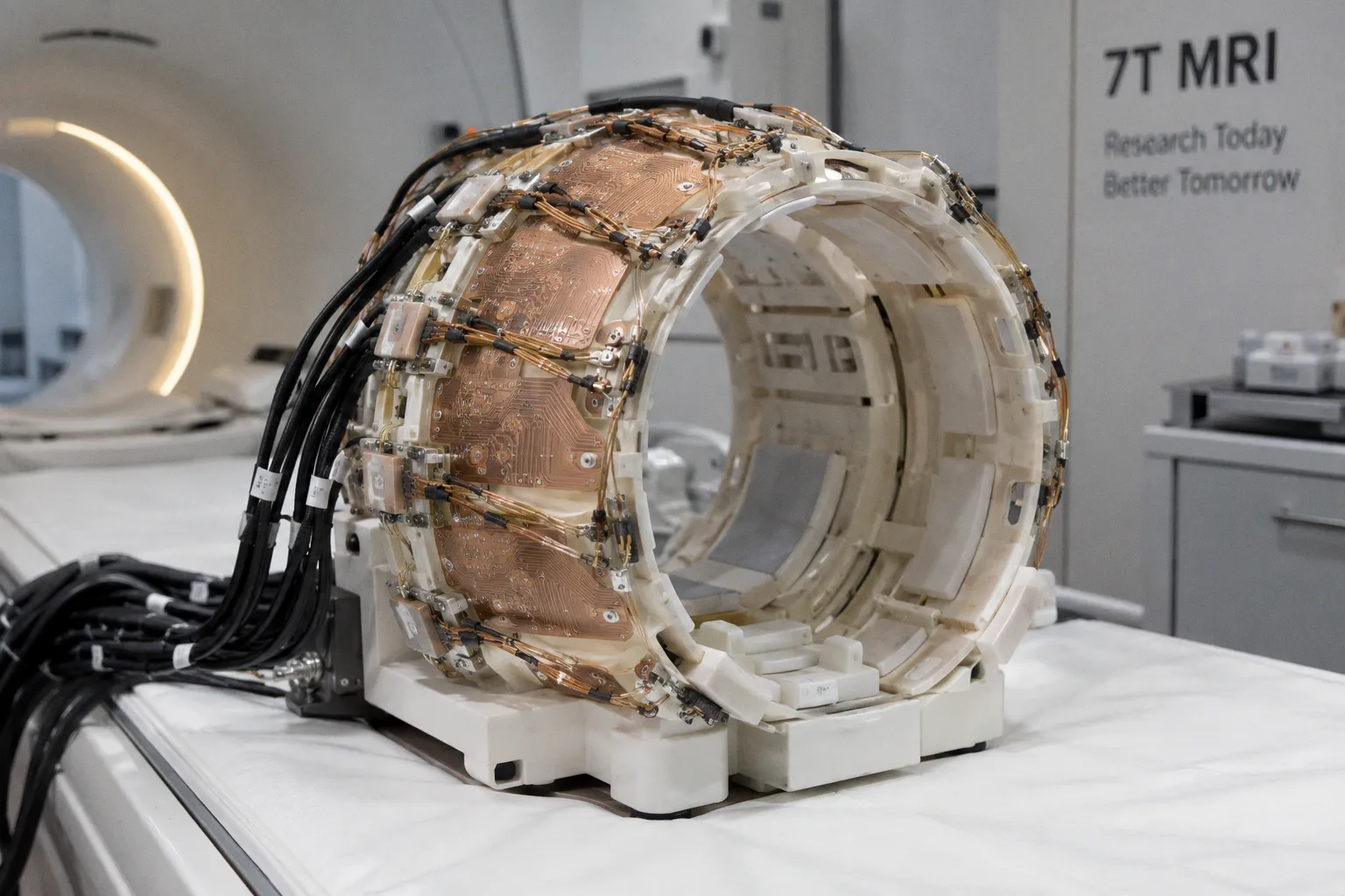
A parallel transmit system uses multiple local transmit elements rather than a single independently driven RF source. Typical configurations include 8, 16, 24, or 32 transmit channels. Each channel contributes a spatially distinct RF field. The system controls the relative amplitude and phase of those channels, and in dynamic implementations it can vary those parameters during the RF pulse.
The total B1+ field is the complex superposition of the individual channel fields. In simplified form, the system seeks channel weights that produce a target excitation pattern:
\[
B_{1}^{+}(\mathbf{r}) = \sum_{n=1}^{N} w_n B_{1,n}^{+}(\mathbf{r})
\]
Here, \(B_{1,n}^{+}(\mathbf{r})\) represents the spatial field produced by transmit element \(n\), and \(w_n\) represents the complex control applied to that element. The equation is not the difficult part. The difficulty lies in measuring the channel fields accurately, selecting a target pattern, constraining local SAR, and delivering the calculated waveform through synchronized RF hardware.
Each additional channel increases the available control space. It does not automatically increase image quality.
A 32-channel array with poor element coupling, unstable calibration, inadequate amplifier headroom, or weak safety optimization can yield less usable performance than a well-designed 8- or 16-channel system. Channel count is a control dimension. It is not a quality metric by itself.
The hardware layers
A clinical pTx implementation spans several tightly coupled layers:
1. Transmit coil geometry.
The array elements must generate sufficiently distinct spatial field patterns. If channels produce nearly redundant fields, the optimization problem has little leverage. Geometry determines what spatial corrections are physically available.
2. Independent RF drive paths.
Each transmit element requires its own controlled RF path. Amplitude and phase cannot be optimized independently if all elements share a single undifferentiated drive chain.
3. Power amplification.
The RF amplifiers must provide synchronized output across channels. Their amplitude range, phase stability, switching behavior, and available power constrain the pulse that can actually be delivered.
4. Transmit synchronization.
Channel timing errors become phase errors. At 7T, those errors directly alter the superposed B1+ pattern. The array is a coherent system. Coherence is not optional.
5. RF calibration.
The system needs a map of how each channel excites the subject. Calibration estimates the local transmit sensitivities used by the pulse optimizer. Poor calibration yields a mathematically valid solution to the wrong electromagnetic problem.
6. Safety supervision.
The system must evaluate RF exposure, including local SAR behavior. Total forward power is not a sufficient surrogate for local heating risk.
The coil is therefore only the visible component. Parallel transmit pTx coil arrays for clinical implementation require an RF chain, calibration framework, pulse controller, reconstruction or sequence integration, and safety model that operate as one instrument.
Transmit and receive arrays solve different problems
A hybrid configuration may use a 16-channel transmit array with a 64-channel receive array. This arrangement is especially relevant to large-field-of-view 7T neuroimaging that extends across the head, neck, and cervical spine.
The transmit array controls excitation. The receive array samples the resulting signal with high spatial encoding capability and improved sensitivity distribution. The two channel counts should not be interpreted as interchangeable performance indicators.
More receive channels can support accelerated acquisition and detailed sensitivity encoding. They do not correct a flawed excitation pattern. More transmit channels provide additional B1+ control variables. They do not guarantee uniformity without a reliable subject-specific calibration and a feasible pulse solution.
| System component | Primary function | Main limitation |
|---|---|---|
| Multi-channel transmit array | Shapes the B1+ excitation field through independent RF drives | Requires calibration, synchronized amplifiers, and SAR-constrained pulse design |
| High-density receive array | Captures signal with spatially distinct sensitivity profiles | Cannot restore tissue that received inadequate excitation |
| RF calibration system | Estimates channel-specific transmit behavior in the subject | Errors propagate directly into the optimized RF pulse |
| Pulse optimizer | Selects amplitude, phase, and waveform controls | Must balance excitation fidelity, duration, power, and local SAR |
| Safety monitor and model | Constrains RF delivery and exposure | Conservative limits can reduce the usable correction range |
Static RF shimming: useful control, limited correction
Static RF shimming is the least complex pTx strategy. The system selects a relative amplitude and phase for each transmit channel and holds those settings constant throughout the RF pulse.
This approach adds spatial control without requiring the full temporal flexibility of dynamic pTx. The optimizer can align the individual channel fields to improve the average excitation pattern over a selected region. It is often a practical first layer of correction.
Static shimming is not a universal solution.
The optimized phase and amplitude set is fixed during the pulse. The system cannot alter the excitation trajectory as the RF pulse progresses. That constrains the spatial degrees of freedom available for correcting difficult B1+ patterns. A static solution may improve homogeneity across one anatomical region while leaving residual shading elsewhere.
The distinction matters most in challenging targets. Static B1 shimming can reduce field variation. It should not be described as eliminating all body 7T shading. Tissue loading, coil geometry, and anatomical extent can exceed the correction capacity of a fixed set of channel weights.
Static shimming is best understood as a constrained spatial compromise. The objective may be to minimize flip-angle error across a region of interest, reduce a signal dropout, or maintain a prescribed excitation level while keeping RF power within limits. The selected objective defines the result.
A solution optimized for mean excitation may tolerate local error. A solution optimized for worst-case error may require higher RF power. A solution optimized for one slice may degrade adjacent coverage. There is no field-uniformity setting detached from a cost function.
What the optimizer is actually balancing
A pTx optimizer typically works against several competing terms:
- Deviation from the target flip-angle distribution.
- RF pulse duration.
- Peak channel amplitude.
- Total or average RF power.
- Local SAR.
- Spatial coverage.
- Robustness to calibration uncertainty.
- Compatibility with the sequence timing budget.
Reducing B1+ error is only one term. A pulse that produces an excellent nominal excitation map but creates unacceptable local SAR is not a clinical solution. A pulse that satisfies SAR but requires a duration incompatible with the repetition time is also not a clinical solution. A pulse that works for one calibration and fails under modest subject variation has poor operational robustness.
The relevant output is therefore not the most uniform simulated field. It is the best feasible pulse under the hardware and safety constraints of the complete scan.
Dynamic pTx and multi-spoke pulse design
Dynamic pTx changes the control variables during RF pulse execution. Channel amplitudes and phases are no longer fixed for the entire pulse. This temporal freedom allows the system to construct a more capable excitation trajectory.
For slice-selective excitation, multi-spoke pulses are a central example. A two-spoke, three-spoke, or four-spoke design uses multiple excitation events with controlled RF weighting and spatial encoding. The system can correct the B1+ field at several points in the excitation process rather than applying one static spatial weighting.
The result is a larger correction space. In difficult anatomical regions, multi-spoke pTx can improve excitation homogeneity beyond single-spoke static shimming and can eliminate signal dropouts that remain under static correction. The gain comes from pulse design, not simply from adding channels.
The cost is complexity.
Dynamic pTx requires:
- More detailed pulse calculation.
- Accurate timing across RF channels.
- Greater integration between calibration, sequence control, and RF amplifiers.
- More demanding SAR estimation.
- Careful management of pulse duration and repetition timing.
- Validation against subject-specific electromagnetic behavior.
The phrase “dynamic” can conceal the actual engineering burden. A dynamic waveform is not merely a static shim repeated with changing numbers. It is a time-dependent control solution delivered through a multi-channel system whose phase, amplitude, and safety limits must remain synchronized.
The trade-off between correction and timing
Every additional spoke creates another opportunity to correct the spatial excitation pattern. It also consumes time and RF energy. If the RF pulse becomes longer, the sequence may require a longer repetition time. That affects scan efficiency and contrast. If the pulse becomes more aggressive, local SAR may rise. If the optimizer reduces power to satisfy SAR, flip-angle fidelity may fall.
This is why parallel transmit pulse design is inseparable from acquisition design. The pulse does not exist in a vacuum. Its duration occupies sequence time. Its power occupies an RF safety budget. Its shape influences slice profile, contrast, and signal stability.
A technically strong solution therefore reports more than a corrected B1+ map. It must establish what was paid for the correction:
- Was the pulse static or dynamic?
- How many spokes were used?
- What anatomical volume was optimized?
- Was the solution robust across subject loading?
- Did the repetition time change?
- What local SAR constraint governed the result?
- Was the improvement maintained across the full field of view?
Without those details, claims of field correction remain incomplete.
Higher channel count expands the solution space. It does not relax Maxwell’s equations, amplifier limits, or local SAR constraints.
Clinical implementation: where hardware becomes a protocol problem
The clinical implementation of pTx begins when the system leaves the engineering bench. A pulse that behaves correctly in simulation must survive calibration variability, patient positioning, anatomy, sequence timing, and safety supervision.
The first requirement is a reliable subject-specific transmit calibration. The scanner must estimate the individual channel contributions under the actual loading condition. Head and neck positioning can alter the relationship between coil elements and tissue. Small changes in geometry can alter the B1+ field and therefore the optimal RF weights.
Calibration uncertainty becomes more consequential as the target correction becomes more aggressive. A modestly robust static shim may tolerate some error. A tightly optimized multi-spoke pulse can be more sensitive to the difference between the assumed and actual field maps.
This creates a practical hierarchy:
1. Measure the transmit field.
2. Define the target excitation volume.
3. Optimize the pulse under RF and SAR constraints.
4. Verify the resulting excitation behavior.
5. Acquire the diagnostic sequence with monitoring active.
Skipping the measurement layer forces the optimizer to operate from an unverified model. Skipping verification leaves no evidence that the delivered excitation matches the calculated solution.
SAR is a spatial constraint, not just a power number
Specific absorption rate is often reduced to a single scanner-reported value. That is inadequate for pTx analysis. The local electric field generated by the multi-channel RF superposition can produce spatially concentrated energy deposition. Two pulses with similar total RF power can generate different local SAR distributions because their channel phases and amplitudes differ.
The same degrees of freedom that improve B1+ uniformity can alter local heating patterns. The optimizer must therefore account for the electromagnetic coupling between channels and tissue. Higher channel counts do not automatically eliminate local SAR hot spots. They can provide more control, but that control must be used within an explicit safety optimization framework.
The relevant safety model may constrain:
- Local SAR in specific tissue regions.
- Whole-head or whole-body SAR, depending on the application.
- Peak RF amplitude per channel.
- Average RF power over the sequence.
- Duty cycle and repetition-dependent exposure.
- Uncertainty in the electromagnetic field estimate.
Conservative safety constraints can reduce the available correction. That is not a failure of pTx. It is the physical boundary of the clinical implementation. A pulse that produces the ideal flip angle only by exceeding a local SAR limit is not a better pulse. It is an invalid one.
Signal dropouts are not all the same
A visible dark region at 7T may originate from transmit cancellation, receive sensitivity, motion, susceptibility, sequence timing, or reconstruction behavior. pTx primarily addresses the transmit-field component. It does not convert every signal dropout into a B1+ problem.
This distinction matters in protocol debugging. If a dropout remains after transmit correction, the next layer may be receive sensitivity, motion correction, susceptibility compensation, or a sequence-specific artifact. A pTx coil array should not be evaluated by whether it makes every intensity defect disappear. It should be evaluated by whether it stabilizes the excitation field in the regions where B1+ variation is the limiting mechanism.
A useful implementation workflow separates the measurements:
- B1+ mapping for transmit-field uniformity.
- Receive sensitivity assessment for signal reception.
- Phantom or subject repeatability testing for calibration stability.
- SAR monitoring for RF safety behavior.
- Sequence-level image analysis for final diagnostic effect.
This prevents a common category error: judging a transmit solution solely from the final magnitude image without identifying which part of the signal chain produced the change.
Head, neck, and cervical spine coverage
Large-field-of-view neuroimaging is a demanding application for pTx. A head-only transmit solution may provide strong local control but fail to maintain excitation across the neck and cervical spine. Extending coverage changes the coil geometry, the loading distribution, and the optimization volume.
A dedicated 16-channel transmit array combined with a high-density 64-channel receive array can support broad 7T coverage across the head, neck, and cervical spine. The configuration separates the demands of excitation control from the demands of signal reception. It also increases the calibration burden.
Broad coverage introduces several constraints:
- The B1+ field must be controlled over a larger and more heterogeneous volume.
- The desired excitation may vary between brain, neck, and spine regions.
- Local SAR behavior may become less uniform across the extended anatomy.
- Subject positioning becomes more consequential.
- A pulse optimized for the brain alone may not perform adequately inferiorly.
The correct question is not whether a coil has a large nominal field of view. It is whether the transmit solution preserves the required excitation quality across the actual protocol volume while satisfying timing and safety constraints.
For neuroimaging, this can affect more than visual uniformity. Spatially varying flip angle changes signal scaling, saturation behavior, magnetization transfer effects, and quantitative comparability across regions. A correction that appears modest in a conventional anatomical scan may be material in spectroscopy, quantitative mapping, diffusion protocols, or longitudinal research where regional consistency matters.
What a credible pTx performance claim must contain
The field has accumulated many descriptions of pTx hardware that stop at channel count. That is an incomplete specification. A credible assessment should identify the physical and computational conditions under which the result was obtained.
At minimum, the report should state:
- Static field strength and target anatomy.
- Transmit and receive channel configuration.
- Coil geometry and coverage.
- Static RF shimming or dynamic pTx.
- Number of spokes, where applicable.
- B1+ calibration method and timing.
- Target flip angle and optimization volume.
- RF pulse duration and sequence timing impact.
- SAR constraints and safety model.
- Whether the result was subject-specific or population-robust.
- The metric used to define improvement.
The metric itself must be explicit. Mean flip-angle error, spatial standard deviation, worst-case deviation, dropout volume, and diagnostic image quality do not measure the same outcome. A pulse may improve one and degrade another.
For developers building acquisition software, the integration boundary is equally important. The pTx controller must receive calibrated field information, expose the necessary amplitude and phase controls, enforce hardware limits, and return a pulse that the sequence can execute. For clinical users, the relevant output is not the elegance of the optimizer. It is the stability of the acquired data under routine positioning and normal anatomical variation.
The near-term direction: more control, not less physics
The trajectory of 7T hardware is clear in one narrow sense. More transmit channels, denser receive arrays, improved calibration, and dynamic pulse design provide more control over the RF excitation problem. Hybrid systems such as 16-channel transmit with 64-channel receive are a logical extension of that architecture.
But increased control also increases the number of failure modes. More channels create more calibration parameters. More independent RF paths create more synchronization requirements. More aggressive pulse design increases the need for accurate SAR modeling. The system becomes more capable and less forgiving.
The practical frontier is therefore not channel count alone. It is robust closed-loop coordination between:
- Electromagnetic field measurement.
- Subject-specific pulse optimization.
- Multi-channel RF delivery.
- Local SAR supervision.
- Sequence timing.
- Reconstruction and quantitative image analysis.
A pTx system that improves B1+ homogeneity but cannot maintain that improvement across subjects is operationally weak. A system that achieves excellent correction only with excessive pulse duration may compromise the protocol. A system that produces a nominally uniform field while exceeding local SAR limits is not clinically deployable.
The physical audit remains blunt. At 7T, radiofrequency field inhomogeneity is a hardware-and-pulse-design problem. Receive correction cannot solve it after the fact. Static shimming can reduce it but may not contain it. Dynamic multi-spoke pTx expands the correction space, provided the RF chain, calibration, optimization, and safety model are engineered as one system.
Parallel transmit coil arrays do not make ultra-high-field MRI simple. They make the underlying constraints addressable. That is the standard they should be judged against.