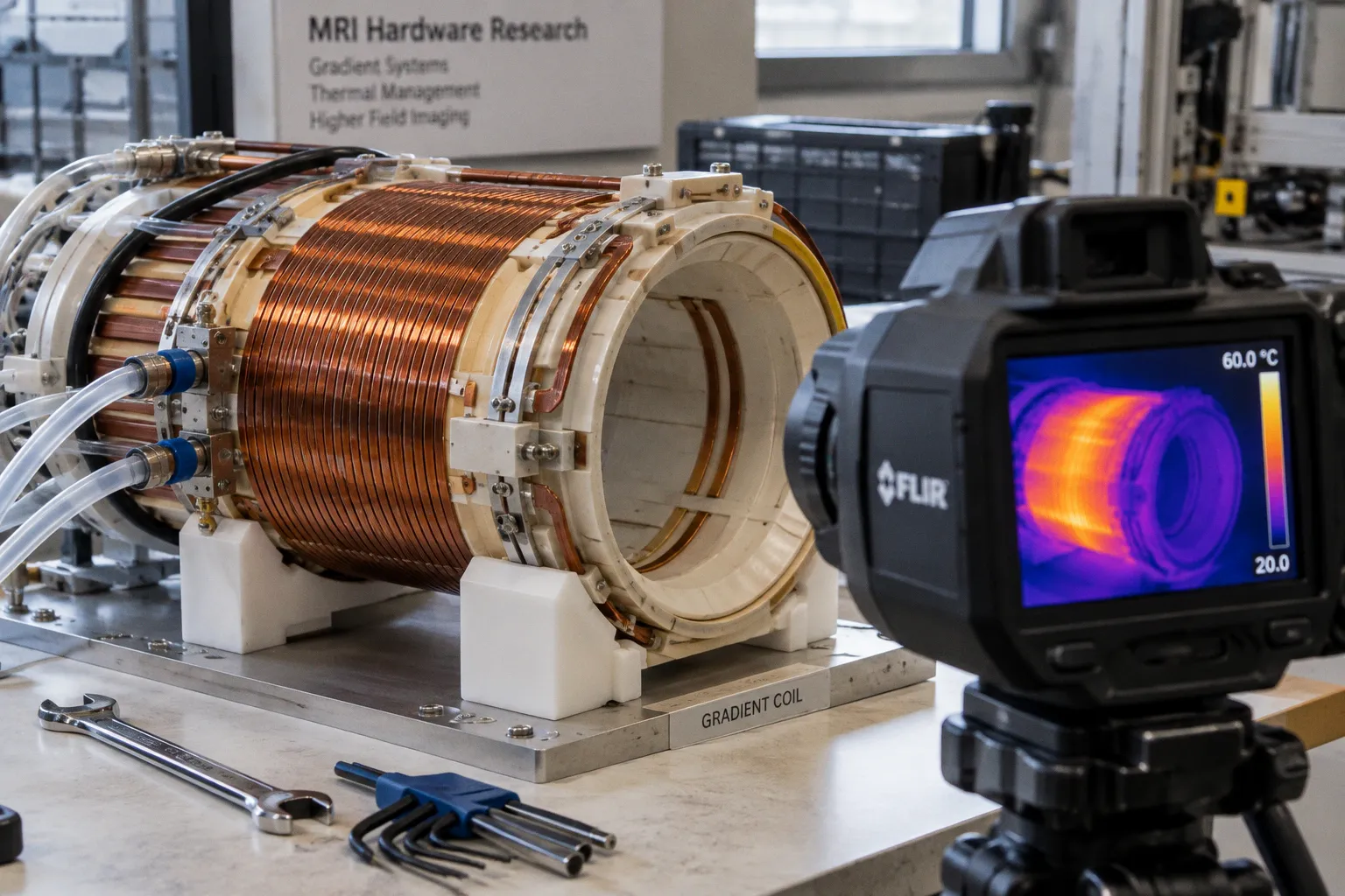
This is not a design flaw—it is resistive heating imposing its physical limit on every high-field system in clinical operation.
The Physics of Resistive Losses and R^5 Scaling
Gradient coils generate magnetic fields by switching large currents through copper windings. The process produces heat. Joule losses—resistive heating from current flow through conductors—dominate the thermal budget of the gradient set. Eddy currents induced in surrounding metallic structures contribute, but the primary heat source remains the conductor resistance itself.
The physics scales brutally with coil geometry. Power dissipation in a gradient coil increases approximately with the fifth power of the coil radius, R^5. Doubling the bore size does not double the thermal load. It multiplies it by roughly 32. This scaling law governs the fundamental tension in MRI hardware design: clinical and research demand pushes toward larger bore diameters for patient comfort and compatibility with hybrid imaging systems, while the thermal penalty of that expansion grows superlinearly.
At high field strengths—3T and above—this constraint sharpens further. Gradient amplifiers deliver peak currents exceeding 1,000 A at voltages reaching several thousand volts. The duty cycle of rapid pulse sequences, particularly echo-planar imaging used in functional MRI, sustains near-maximum gradient switching for extended periods. Each switching event deposits resistive heat. Each repetition adds to the thermal load. The system accumulates energy faster than passive conduction alone can remove it.
The result is a hard operational ceiling. Push the gradient set beyond its thermal budget, and the software intervenes—reducing gradient amplitude, extending rise times, or delaying the next sequence entirely. The physicist does not choose this. The physics does.
Active Cooling Architectures: Managing Heat Dissipation in High-Duty Cycles
Modern MRI scanners do not rely on passive convection. The thermal loads generated by high-duty-cycle gradient operation demand active fluid cooling as a mandatory system component—not an optional enhancement.
The standard architecture circulates a coolant—typically deionized water or a water–ethylene glycol mixture—through channels integrated into the gradient coil former. The fluid enters the gradient bore at approximately 20 °C and exits at up to 30 °C under sustained high-demand imaging. That 10-degree differential represents the heat extracted per pass. The chiller unit, external to the scanner room, re-cools the fluid and recirculates it continuously.
The engineering challenge is not trivial. Cooling channels must be positioned close enough to the copper windings to conduct heat efficiently, yet they must not introduce susceptibility inhomogeneities or acoustic coupling that would compromise image quality. Channel geometry, flow rate, and coolant viscosity all constrain the achievable thermal transfer rate. The system is optimized within a narrow band of operating parameters—stray outside it, and cooling efficiency degrades nonlinearly.
High-duty-cycle sequences—diffusion-weighted imaging, cardiac MRI, real-time interventional guidance—saturate the cooling system's capacity. The fluid loop was designed for a specific heat dissipation target. Exceed it, and the gradient coil temperature climbs toward its operational limit. The scanner does not fail gracefully. It constrains.
Acoustic noise generation is not incidental to this discussion—it is physically coupled. Lorentz forces acting on the current-carrying conductors produce 110–120 dB of acoustic pressure during echo-planar sequences. Those same conductors dissipate resistive heat. Noise and heat share a common origin in the physics of gradient switching. Any mitigation strategy that addresses one without the other is incomplete.
The R^5 power scaling law means a larger-bore MRI system does not carry a linearly larger thermal burden—it carries an exponential one. Every millimeter of coil radius purchased for patient comfort is paid for in cooling infrastructure.
The following parameters govern thermal management in modern high-field gradient systems:
- Coolant composition: Deionized water or water–ethylene glycol mixture, selected for electrical insulation and thermal capacity
- Inlet temperature: Approximately 20 °C, maintained by external chiller units
- Outlet temperature: Up to 30 °C under sustained high-duty-cycle imaging
- Peak gradient amplifier current: Exceeds 1,000 A during rapid switching events
- Peak amplifier voltage: Reaches several thousand volts
- Maximum internal coil temperature: 55–60 °C before thermal monitoring algorithms throttle performance
- Acoustic noise output: 110–120 dB during EPI sequences, a direct mechanical consequence of Lorentz forces on conductors carrying thermal loads
The last item deserves emphasis. The relationship between acoustic noise and thermal load is not correlative—it is causal. Both arise from the same electromagnetic interaction between current and magnetic field. Reducing gradient slew rate lowers both noise and heat, but at the cost of temporal resolution. There is no decoupled solution.
Thermal Instability and Its Impact on Passive Shims and RF Detuning
Heat does not stay contained within the gradient coil. It propagates outward. And the components it reaches are not thermally tolerant.
Passive magnetic shims—ferromagnetic elements positioned during installation to correct B₀ field inhomogeneity—lose magnetization as their temperature rises. The effect is direct and measurable. As shim temperature increases, the center frequency of the MR system drifts. Field homogeneity degrades. Spectral resolution in MR spectroscopy narrows. Fat-water separation in Dixon-based sequences becomes unreliable. The shims were set during commissioning at room temperature. When the gradient coil surrounding them reaches 55 °C, the thermal environment has shifted, and the shim correction no longer holds.
The radiofrequency transmitter coil suffers a parallel degradation mechanism. Capacitance values in the RF tuning network are temperature-dependent. As the gradient coil heats the surrounding bore environment, the RF coil's resonant frequency shifts. Transmitter efficiency drops. B₁ field uniformity degrades. Flip angle calibration, performed at the start of the examination, becomes inaccurate by the session's end if the thermal environment has changed significantly.
Neither failure mode is catastrophic in isolation. Both are cumulative. A scan session that begins with calibrated shims and tuned RF performance may conclude with measurable drift in both parameters. The physicist who commissioned the system knows this. The clinician acquiring images thirty minutes later may not.
Passive shims calibrated at room temperature lose validity as the gradient coil climbs toward 55 °C. The center frequency drifts. The field homogeneity degrades. This is not a rare edge case—it is the standard thermal physics of every high-field system under sustained load.
The scanner's thermal monitoring software provides a buffer. When internal temperature sensors detect the approach toward the 55–60 °C threshold, the system throttles gradient performance before physical damage occurs. But throttling is not a solution—it is a concession. The scan planned at maximum gradient amplitude and minimum rise time now runs at reduced specifications. Temporal resolution in cardiac imaging drops. Diffusion encoding b-values are limited. The clinical protocol that justified the expensive high-performance gradient option is now constrained by the thermal budget of the hardware executing it.
This is the hidden cost of thermal saturation. It is not measured in degrees Celsius alone—it is measured in degraded protocol fidelity. Sequences designed for the scanner's peak performance are quietly revised by the machine's own safety logic into something less capable. The physicist reviewing the images may not see explicit warnings. The degradation is subtle: slightly lower SNR, slightly coarser temporal resolution, slightly less accurate fat-water separation. Thermal throttling does not announce itself loudly. It erodes.
Material Innovations: Alumina-Ceramic Formers and Thermal Conductivity
The gradient coil former—the structural cylinder on which the copper windings are wound—plays a critical role in heat transfer. Its thermal conductivity directly determines how efficiently resistive heat moves from the conductors to the cooling channels.
Traditional formers use plastic-fiberglass composites. These materials are mechanically adequate and electrically insulating, but their thermal conductivity is poor. Heat generated in the copper windings must traverse a low-conductivity barrier before reaching the cooling fluid. The temperature gradient across the former wall creates a thermal bottleneck: the copper side runs hot while the coolant side remains relatively cool. The average coil temperature climbs unnecessarily.
Alumina-ceramic materials offer a fundamentally different thermal profile. Their thermal conductivity exceeds that of plastic-fiberglass composites by a significant margin. Heat transfers more efficiently from the windings through the former to the cooling channels. The internal temperature of the gradient coil drops for the same input power and coolant flow rate. The operational ceiling rises.
The tradeoff is not without consequence. Ceramic materials are brittle. They do not tolerate the mechanical vibration and acoustic stress generated by Lorentz forces during rapid gradient switching as gracefully as composites. Integration into the gradient assembly requires careful mechanical design to prevent cracking under cyclic acoustic loading. Manufacturing tolerances tighten. Unit cost increases.
| Property | Plastic-Fiberglass Composite | Alumina-Ceramic |
|---|---|---|
| Thermal conductivity | Low — creates a bottleneck at the conductor-fluid interface | Substantially higher — enables efficient heat transfer to cooling channels |
| Mechanical resilience | Tolerates vibration and acoustic loading well | Brittle; requires careful mechanical integration and dampening |
| Electrical insulation | Adequate | Adequate |
| Manufacturing complexity | Lower | Higher; tighter tolerances required |
| Temperature gradient across former wall | Steep — copper side runs significantly hotter than coolant side | Reduced — more uniform temperature distribution through the wall |
The trend in high-performance gradient coil design points in one direction. As bore sizes increase—scaling thermal load by R^5—and clinical protocols demand higher duty cycles, the material properties of the former become a binding constraint. Alumina-ceramic is not a luxury specification. It is a thermal engineering necessity for systems operating at the upper boundary of their performance envelope.
Gradient amplifier technology has evolved alongside these material changes. Modern amplifiers deliver peak currents exceeding 1,000 A and voltages reaching several thousand volts with increasing efficiency, but they also push more power through the coil per unit time. The thermal budget is not static—it grows with each generation of faster, more powerful gradient hardware. Material innovation in the former must keep pace, or the thermal ceiling becomes the limiting factor in system performance regardless of amplifier capability.
Eddy Current Induction and Localized Heating in Metallic Implants
Gradient switching does not only heat the coil itself. It induces eddy currents in any conductive structure within the changing magnetic field. In the scanner bore, these structures include the cryostat shields, the RF screen, and—critically—any metallic implant within the patient.
Research published in the Journal of Magnetic Resonance Imaging demonstrated that gradient-switching-induced eddy currents can elevate temperatures by more than 10 °C in isolated copper structures, even without RF power applied. This is a gradient-only heating mechanism. It operates independently of the specific absorption rate constraints that govern RF deposition in tissue. It is a distinct thermal risk vector with its own physics.
The clinical implication is direct. Patients with metallic implants—orthopedic hardware, surgical clips, certain cardiac devices—expose those conductive structures to rapidly changing magnetic fields during every gradient switching event. The implant absorbs energy through electromagnetic induction. Its temperature rises. The surrounding tissue bears the thermal consequence.
Current MRI safety protocols address RF-induced SAR heating thoroughly in implant screening procedures. Gradient-induced eddy current heating receives less standardized attention, partly because the temperature distribution is highly localized and dependent on implant geometry, orientation, and electrical connectivity. A small, isolated metallic fragment presents a different thermal risk profile than a long conductive wire or a contiguous metallic plate. The physics is sensitive to geometry in ways that resist simple categorical screening rules.
The physics constrains the solution space. Suppressing eddy current heating requires reducing the rate of change of the magnetic field—dB/dt—which means reducing gradient slew rates. But reduced slew rates degrade the temporal resolution that many advanced sequences depend on. The gradient physicist faces a familiar tradeoff: performance versus safety, mediated by thermal limits.
Gradient-switching-induced eddy currents can exceed 10 °C of localized heating in conductive structures—without any RF power applied. This is a distinct thermal risk vector that operates independently of SAR safety limits and demands its own screening logic.
This distinction matters for safety screening. A metallic implant that passes SAR-based safety evaluation may still be exposed to gradient-induced thermal loads that the screening process does not explicitly quantify. The two heating mechanisms—RF absorption and gradient eddy current induction—have different spatial distributions, different temporal profiles, and different dependencies on implant geometry. Treating them as a single risk category is a simplification the physics does not support.
The Thermal Ceiling as a Design Constraint
Three facts govern the thermal reality of every high-field MRI gradient system currently in clinical operation.
First, resistive heating scales with R^5. Larger-bore systems pay an exponential thermal price for their geometry. Second, active fluid cooling is mandatory—not optional, not an enhancement. Without it, the gradient coil reaches its thermal ceiling within minutes of sustained high-duty-cycle operation. Third, heat propagates beyond the coil itself: it degrades passive shims, detunes RF circuits, and can induce dangerous localized heating in conductive implants through eddy current mechanisms that operate independently of RF safety limits.
The thermal limit is not a line to be crossed at the operator's discretion. It is a physical boundary enforced by material properties, fluid dynamics, and electromagnetic induction. The scanner's thermal monitoring software does not negotiate with the physics—it concedes to it, throttling performance to protect hardware integrity. Every protocol designed for high-performance gradients must account for this ceiling, or it will be revised by the machine itself.
The direction of engineering effort is clear. Alumina-ceramic formers improve thermal conduction from windings to coolant. Optimized channel geometries increase fluid cooling efficiency. But the fundamental constraint remains: switching kiloampere currents through copper windings at kilohertz rates generates heat, and scaling coil radius demands paying the R^5 penalty. The physicist who designs the acquisition protocol must work within these limits. The limits do not adjust to the protocol.