Once the anatomy becomes electrically large, the transmit field stops behaving like a smooth, quasi-static B1 distribution. It behaves like a wave. Standing-wave patterns develop, constructive interference concentrates power in some regions, and destructive interference suppresses signal in others.
This is the core of the dielectric resonance problem. The resulting artifact is deterministic and geometry-dependent, but it cannot be removed through sequence tuning alone. Changing the flip angle, acceleration factor, or contrast preparation may alter how the problem appears; it does not remove the underlying field pattern. The correction has to involve RF hardware, field control, or both.
The Physics of 297 MHz: Why Wavelength Shrinkage Disrupts 7T Imaging
The Larmor relationship for hydrogen gives an operating frequency of approximately 297.2 MHz at 7T. For comparison, the corresponding frequencies at 1.5T and 3T are approximately 63.9 MHz and 127.8 MHz. As field strength rises, the RF wavelength in tissue becomes shorter and increasingly comparable to the dimensions of the anatomy being imaged.
At lower field strengths, it is often reasonable to treat the transmit field as relatively uniform across a head-sized volume. That assumption becomes unreliable at ultra-high field. The head is no longer small compared with the electromagnetic wavelength, so the RF field interacts with the anatomy as a distributed electromagnetic structure rather than as a simple excitation envelope.
Two effects dominate.
Dielectric resonance inside tissue
Brain tissue has a high relative permittivity at the operating frequency. Around 300 MHz, values for brain tissue are commonly described as being in the range of ε_r 50–60. This property influences how the electric and magnetic components of the RF field propagate through the head.
The tissue does not simply absorb the incoming RF energy. It stores and redirects part of that energy. Displacement currents form within the tissue, and their interaction with the transmit field creates spatially varying patterns. In practical terms, the RF field can become stronger in one part of the brain and weaker in another without any change in the prescribed sequence.
Interference at tissue boundaries
The brain is not an electrically uniform object. Gray matter, white matter, cerebrospinal fluid, bone, muscle, and air interfaces all have different electromagnetic properties. Reflections and phase changes at these boundaries alter the local field.
The resulting B1+ distribution contains peaks and nulls. A region near a constructive-interference peak may receive more excitation than intended, while another region at a destructive node may receive too little. The nominal flip angle shown in the sequence prescription is therefore not the flip angle experienced uniformly across the brain.
At 7T, the head is no longer electrically small. It is a dielectric resonator, and the transmit field behaves accordingly.
This is why dielectric resonance effects in 7T MRI are not merely cosmetic shading artifacts. They affect the validity of quantitative measurements. T1 mapping, diffusion protocols, magnetization-transfer methods, susceptibility imaging, and other sequences that rely on a controlled excitation can inherit spatial bias from the B1+ field.
The problem also has a safety dimension. A field maximum can coincide with increased local electric-field deposition, creating a SAR concern even when the whole-head average appears acceptable. Global power and local power are not interchangeable measures at ultra-high field. The spatial pattern matters.
Anatomical Signal Voids: Mapping B1+ Inhomogeneity in the Temporal Lobes and Cerebellum
The field pattern is not random noise. It is shaped by head geometry, tissue composition, coil loading, and the position of the anatomy inside the RF field. Certain regions are especially vulnerable in 7T head imaging.
Temporal lobes
The temporal lobes are positioned laterally, away from the geometric center of the head. Depending on the coil and excitation strategy, these regions can fall close to B1+ minima. The result is a loss of signal or contrast that may be more severe than the raw anatomical image suggests because the local flip angle has also changed.
This creates a difficult failure mode. The temporal lobe may still be visible, but its signal intensity no longer has the expected relationship to neighboring tissue. A sequence can appear technically complete while producing data that are poorly suited to comparison across subjects or to quantitative analysis.
The effect is particularly disruptive in protocols that depend on consistent contrast across both hemispheres. A correction that improves the center of the brain but leaves the temporal regions under-excited may produce a visually cleaner image without actually solving the measurement problem.
Cerebellum and posterior fossa
The cerebellum sits in the inferior posterior fossa, another region that can be affected by destructive interference. Cerebellar imaging is important in neuroscience, motor-system studies, and disease-focused protocols, yet the region is often difficult to optimize with a head coil designed around central-brain performance.
The inferior position of the cerebellum introduces additional practical complications. The coil geometry, neck position, dielectric interfaces, and the transition between head and surrounding structures all influence the local field. A setup that performs well for cortical imaging may therefore leave the posterior fossa with reduced excitation or uneven contrast.
A bright central region may appear at the same time as peripheral signal loss. That central brightening is not simply a gain in useful signal. It can indicate that the local flip angle is higher than prescribed, with possible consequences for contrast behavior and local SAR.
Why the pattern moves between patients
The location of a null is determined by more than the nominal field strength. Head size, shape, tissue distribution, positioning, coil loading, and the presence of air or fluid interfaces all change the electromagnetic boundary conditions. A pad or resonator that improves one subject may be less effective when the anatomy or placement changes.
That variability is why B1 field inhomogeneity at ultra-high field should be mapped rather than inferred from a single reference scan. A conventional anatomical image shows the consequence of the field problem; a B1 map helps identify its source and indicates whether the correction is working in the region that matters for the protocol.
Passive RF Shimming: Leveraging High-Permittivity Dielectric Pads to Restore Contrast
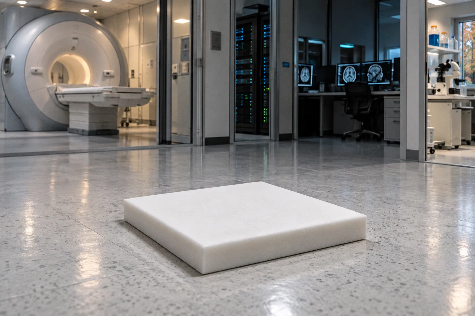
The most accessible form of dielectric correction is passive RF shimming. High-permittivity dielectric pads are placed near the head, usually adjacent to the regions where the transmit field is weak. Calcium titanate suspensions are one example of the materials used in this approach, with relative permittivity values around ε_r 110 in relevant designs.
The pad does not generate an independent RF waveform. Instead, it changes the local electromagnetic boundary conditions when the transmit field is applied. Displacement currents inside the pad produce secondary field effects that reshape the original interference pattern.
In a well-positioned setup, the pad can move or weaken a destructive node near the temporal lobes, improve excitation in a peripheral region, or redistribute the field away from an unfavorable concentration. The goal is not necessarily to make the field mathematically flat everywhere. The practical goal is to improve the field in the anatomy that the protocol actually uses while keeping the resulting power deposition within acceptable limits.
Placement is part of the hardware design
A dielectric pad is often described as a material solution, but its placement is equally important. The distance from the scalp, the pad’s orientation, its coverage, and its position relative to the coil all affect the result. Even the way the pad is supported can matter if it changes the gap between the material and the head.
This makes passive shimming more hands-on than the word passive suggests. The material has no active control loop, but the technologist still has to reproduce a physical configuration. A protocol that uses a pad should document placement in a way that can be repeated across sessions and operators.
The optimal position also depends on the target anatomy. A pad intended to improve temporal-lobe excitation may not be the best choice for a cerebellar protocol. A broad pad can influence a larger volume, but a more focused design may provide better control over a specific region. There is no universal pad geometry that corrects every head and every sequence equally well.
What passive pads can and cannot do
Passive pads are attractive because they do not require a new transmit chain or a complex per-subject optimization process. They can be introduced into an existing workflow, and their effect is immediate once the physical setup is correct.
Their limitation is the same feature that makes them simple: the correction is fixed after placement. The pad cannot respond to a new subject, a different head position, or a sequence with a different excitation pattern. Results vary with anatomy, placement, coil loading, and protocol. A configuration that works well in one study should therefore be treated as a reproducible setup to validate, not as a universal performance guarantee.
Passive dielectric shimming exchanges electronic complexity for physical discipline. It can be effective, but the correction is only as reliable as the geometry that produces it.
The pad also changes more than the desired B1+ profile. It may alter local electric fields, loading, coupling, and SAR. Any implementation should be evaluated with the intended coil, sequence, and positioning method rather than transferred directly from a different hardware configuration.
Active Control: Parallel Transmit and Channel Phase Manipulation
When passive correction cannot provide enough control, parallel transmit offers a more flexible approach. A pTx system uses multiple independently controlled RF transmit channels. Each channel drives a separate coil element, and the relative amplitude and phase of those channels can be adjusted to shape the combined B1+ field.
The underlying principle is straightforward: each transmit element produces its own spatial field pattern, and the scanner combines them. By selecting appropriate channel weights, the system can reinforce excitation in a region that would otherwise be close to a null while reducing excitation where the field is already excessive.
Magnitude and phase are both important
Phase manipulation is central to pTx because the problem at 7T is fundamentally an interference problem. Two coil elements may produce fields that add constructively in one location and destructively in another. Changing the phase relationship between them changes that spatial pattern.
Amplitude control determines how strongly each element contributes. Phase control determines how those contributions align. The optimization therefore has to consider the full complex B1+ field, not just the magnitude of the signal measured in a reference image.
Magnitude least-squares methods and related optimization strategies seek channel settings that bring the achieved field closer to a target distribution. The target may be a uniform excitation across a volume, a tailored profile for a specific anatomy, or a compromise that balances field homogeneity against RF power and local SAR.
Calibration is not optional
The flexibility of pTx comes with an operational burden. Before the final acquisition, the system needs information about the transmit field produced by each channel. Calibration scans estimate the spatial response of the coil elements, after which the optimization calculates a suitable set of channel amplitudes and phases.
That calibration is affected by the subject and the setup. A change in head position, coil loading, padding, or anatomy can alter the result. The transmit solution must therefore be treated as part of the scan configuration rather than as a permanent property of the scanner.
Safety calculations also become more involved. A change in channel phase can move an electric-field maximum even if the total applied power remains similar. SAR supervision must account for the channel combination and for the possibility of local deposition. A field solution that improves B1+ uniformity but creates an unacceptable local maximum is not a successful solution.
pTx versus passive dielectric correction
Passive pads and pTx are often presented as competing methods, but they solve different parts of the same problem.
| Approach | Main strength | Main limitation | Best use |
|---|---|---|---|
| High-permittivity dielectric pad | Simple physical correction that can improve a known weak region | Fixed after placement and sensitive to geometry | Reproducible protocols with a stable target anatomy |
| Parallel transmit | Subject- and sequence-specific control of the transmit field | Requires calibration, optimization, and detailed RF safety management | Research protocols that need tailored excitation |
| Hybrid pad plus pTx setup | Uses the pad to reduce the burden on active shimming | Adds hardware and workflow complexity | Difficult anatomies or demanding quantitative acquisitions |
In a hybrid setup, the passive component handles part of the gross field redistribution, while pTx corrects the remaining variation. This can be more practical than asking the active system to compensate for the entire dielectric pattern. It can also reduce the range of channel settings required by the optimizer, although the final result still depends on calibration and safety verification.
The important point is that no single homogeneity value defines success for every protocol. A field that is adequate for a qualitative anatomical sequence may be insufficient for quantitative mapping. Conversely, a highly uniform solution may require more RF power than a protocol can justify. The target has to be defined by the measurement, not by the appearance of one representative image.
Optimizing SAR and SNR: Integrating Dielectric Resonators with Wearable Coil Arrays
The next step is to bring dielectric structures closer to the receive and transmit elements. Instead of using a separate pad placed beside the head, researchers can integrate high-permittivity resonators into a wearable coil housing or array.
Materials based on barium titanate and related ceramics can provide very high relative permittivity. Designs using resonators with ε_r around 1070 have been studied in combination with twisted-pair wearable coils. The resonator changes the near-field distribution, while the coil geometry is intended to preserve useful coupling and reduce common-mode current losses.
A phantom study of this type of configuration reported a 250% increase in peripheral SNR and a 23% increase in central SNR compared with a conventional coil configuration. In human voxel simulations, the same general design reduced peak 10g SAR by 25.8%. These values belong to that specific resonator-and-coil configuration; they should not be treated as universal gains for every high-permittivity material or head coil.
The engineering significance is broader than the individual numbers. A resonator placed close to a target region can redistribute the RF field before it is attenuated by distance and tissue loading. It can also change the relationship between transmit efficiency, receive sensitivity, and local power deposition. The useful design is therefore not simply the one with the highest permittivity. It is the one that produces a favorable field pattern in the anatomy of interest without creating a new SAR problem.
Wearable arrays and the receive-field problem
Receive arrays introduce another layer of complexity. A coil may have good nominal sensitivity but still produce uneven signal because of coupling, cable currents, element interaction, or poor conformity to the head. Twisted-pair conductors and other common-mode suppression strategies address part of this problem, while dielectric resonators modify the local electromagnetic environment.
The combination can be valuable at 7T because signal loss is often regional rather than uniform. Improving a weak peripheral region may produce a larger practical benefit than adding sensitivity to the already bright center. This is especially relevant for the temporal lobes, inferior brain, and posterior fossa.
However, SNR should not be considered independently from contrast and field calibration. A local increase in signal does not automatically restore the intended flip angle. Nor does a visually brighter region prove that the quantitative bias has been removed. Transmit-field mapping, receive sensitivity characterization, and sequence-specific validation remain necessary.
Inductively coupled resonator arrays
A separate strategy uses inductively coupled RF resonator arrays. These resonators couple to the receive elements without requiring every resonator to be hard-wired into the scanner’s transmit chain. Their geometry can be tuned to enhance sensitivity in a region where the conventional coil performs poorly.
Cerebellar applications are a natural target because the posterior fossa can coincide with a dielectric signal void. Reported designs have produced a 2–4× SNR improvement in the cerebellum. As with the wearable-coil results, that performance depends on the resonator arrangement, coupling, anatomy, sequence, and comparison coil. The figure describes a regional improvement, not a uniform gain across the entire head.
Inductive coupling also creates design questions. The resonators must remain stable during positioning, avoid excessive interaction with neighboring elements, and preserve safe behavior across the intended range of loading conditions. A resonator that performs well in a phantom may need substantial mechanical and electromagnetic refinement before it can become a routine clinical accessory.
Comparing the hardware options
| Configuration | Primary effect | Practical interpretation |
|---|---|---|
| Separate high-permittivity pad | Reshapes the local transmit field through displacement currents | Useful when the target region and placement can be reproduced reliably |
| Dielectric resonator integrated with a wearable coil | Combines local field control with receive-array sensitivity | Promising for peripheral regions, but closely tied to coil and housing design |
| Inductively coupled resonator array | Adds regional receive sensitivity through magnetic coupling | Particularly relevant to difficult areas such as the cerebellum |
| pTx with a conventional multichannel coil | Actively adjusts the combined B1+ field | Flexible, but dependent on calibration, optimization, and SAR supervision |
| Hybrid dielectric and pTx system | Uses passive redistribution before active correction | Can reduce the correction burden while retaining patient-specific control |
The comparison also clarifies why dielectric resonance cannot be discussed only as an artifact. The same electromagnetic behavior that creates a signal void can be used deliberately. A passive pad, resonator, or coupled array changes the field that the scanner has to manage. The design challenge is to turn an uncontrolled standing-wave pattern into a controlled local resource.
Designing a Reliable 7T Workflow
The hardware is only one part of the solution. A dielectric correction that is effective in a laboratory setup can fail in routine scanning if the workflow does not preserve the geometry on which the correction depends.
A practical 7T protocol should account for several linked variables:
- Head position: Small changes in rotation, tilt, or inferior displacement can move the anatomy relative to a B1+ null.
- Pad or resonator placement: The distance from the scalp and the position relative to the target region should be defined, documented, and reproducible.
- Coil loading: The subject, padding, and accessory hardware all contribute to the electromagnetic load seen by the coil.
- Sequence demands: A solution optimized for one excitation pattern may not transfer to another sequence with a different pulse duration, bandwidth, or flip-angle schedule.
- Transmit-field mapping: The correction should be assessed in the region that drives the scientific or clinical endpoint, not only in a visually convenient slice.
- SAR supervision: Improvements in uniformity must be checked against local and whole-head power deposition.
- Receive sensitivity: A stronger image does not necessarily mean a more accurate transmit field, and a more uniform transmit field does not guarantee uniform receive sensitivity.
This is also where the distinction between a research platform and a clinical workflow becomes important. In a research environment, it may be reasonable to acquire additional calibration data, reposition a pad, or optimize a new pTx solution for every subject. A clinical service needs a procedure that is faster, easier to audit, and less dependent on one operator’s experience.
The best configuration is therefore not always the one that produces the highest isolated SNR. It may be the one that delivers stable performance across operators, sessions, and anatomies while keeping calibration and safety checks manageable.
The Practical Constraint
Dielectric resonance is not an aberration to be eliminated. It is the predictable electromagnetic response of human tissue to RF excitation near 297 MHz. The wavelength inside the head is short, tissue properties vary across the anatomy, and the transmit field develops constructive and destructive regions as a consequence.
What changes is how deliberately the imaging system manages that response.
High-permittivity pads provide a relatively simple physical correction, but their performance varies with anatomy, placement, and protocol. Parallel transmit offers patient-specific control, but it requires calibration, optimization, and careful SAR management. Dielectric resonators and wearable arrays can improve local SNR and field behavior, yet they demand integrated coil design rather than an accessory added at the end of the workflow. Inductively coupled arrays can recover difficult regions such as the cerebellum, provided their coupling and safety characteristics are understood.
The honest reading is that full-quality 7T brain imaging is not only a sequence problem. It is a hardware, field-mapping, and reconstruction problem. The remaining artifacts are often not random failures; they are the predictable result of a coil and correction strategy that was not designed for the anatomy being scanned.
The right question is therefore not whether dielectric resonance can be avoided. It is whether the system can measure, shape, and validate the field where the protocol needs it. At 7T, that is the difference between merely increasing field strength and making ultra-high-field imaging usable.