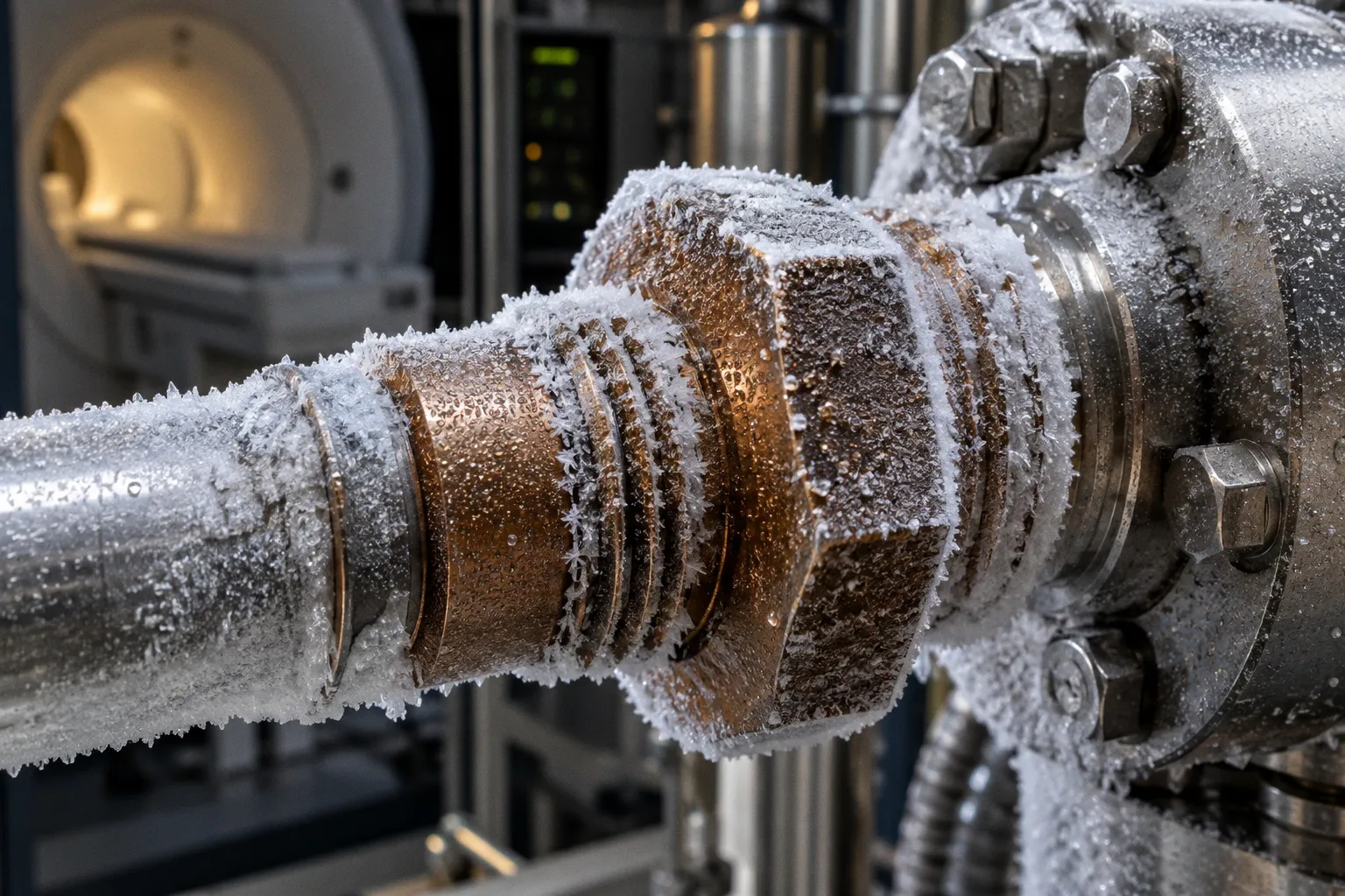
In a superconducting MRI magnet, helium loss is rarely the first failure. It is usually the visible consequence of a thermal problem that started somewhere else: a degraded cold head, a compressor fault, a loss of chilled water, a vacuum failure, or a slow leak in an older cryostat.
That distinction matters. Helium boil-off rates in superconducting MRI magnets are not just a consumables metric. They are a record of how effectively the cryostat is rejecting heat, how much margin remains before the magnet becomes unstable, and how quickly a service team must act when the cooling chain changes.
The familiar reference point is 4.2 K, the approximate boiling temperature of helium at atmospheric pressure. But 4.2 K is not the superconducting transition temperature of the NbTi coil. Nor is it a universal failure threshold. A clinical magnet can remain superconducting above that temperature, depending on the conductor, magnetic field, operating current, and local thermal conditions. The engineering problem is that the available margin narrows as the coil warms, while helium losses and pressure changes accelerate the consequences of every additional watt entering the cryostat.
The cold head runs, the compressor rejects heat, the insulation holds, and the helium remains in the cryogenic circuit. When one link weakens, a stable operating condition can turn into a maintenance event—or, if the warning signs are missed, a quench.
The physics of cryogenic stability at 4.2 Kelvin
Commercial superconducting MRI magnets commonly use NbTi filaments embedded in a copper matrix. The conductor is cooled by liquid helium inside the cryostat. At the nominal bath temperature of approximately 4.2 K, the conductor operates below its critical surface: the combination of temperature, magnetic field, and current density at which superconductivity can no longer be maintained.
The often-quoted value of approximately 9.2 K refers to the zero-field critical temperature of NbTi, not to a universal operating limit for an MRI magnet. Applied magnetic field lowers the effective critical temperature, and the conductor's current-carrying capacity also depends on field and temperature. At the field strengths used in clinical MRI, the coil still has operating margin at 4.2 K, but that margin is a system property rather than a simple five-degree allowance.
The distinction is important in failure analysis:
- 4.2 K is approximately the normal boiling point of helium at atmospheric pressure and a common reference temperature for the helium bath.
- About 2.17 K is helium's lambda point, below which liquid helium enters the superfluid phase. A conventional MRI helium bath near 4.2 K is above this point, not below it.
- The superconducting transition is set by the conductor's field-dependent critical surface. It should not be equated with the helium boiling point.
- A quench occurs when part of the winding becomes resistive and the resulting heat generation spreads faster than the system can remove it. The initiating disturbance may be local and brief; it does not require the entire bath to reach a single temperature threshold first.
The cryostat's job is therefore broader than keeping the helium at a named temperature. It must limit heat ingress from the room-temperature vessel, maintain the vacuum space, intercept radiation with thermal shields, and provide a reliable path for removing heat from the helium reservoir. Multi-layer insulation reduces radiative transfer. The vacuum suppresses gas conduction. Mechanical supports are designed to limit conductive loading without compromising structural stability. Persistent joints are engineered for very low resistance, but their dissipation is not literally zero.
4.2 K is a reference condition, not a magic line between a healthy magnet and an instantly resistive one.
In a stable system, the thermal load is small enough that the helium inventory changes slowly, or the cryocooler can re-condense the vapor as it forms. In an older vented design, the gas leaves the cryostat and must eventually be replaced. In a zero-boil-off system, the gas is captured and returned to the liquid phase. Both architectures depend on the same fundamentals: low heat leak, sound insulation, controlled pressure, and instrumentation that reveals drift before it becomes a crisis.
The magnetic field adds another layer of sensitivity. A superconducting coil is not simply a cold copper wire with better efficiency. Its critical current density falls as the operating point approaches the conductor's limits. Local heating, mechanical motion, and changes in current distribution can therefore matter even when an average temperature reading appears acceptable. A magnet may remain superconducting while its field stability, drift behavior, or homogeneity begins to change. That is why a cooling alarm should not be interpreted only as a binary question of whether the scanner has quenched.
Legacy systems and the baseline of helium boil-off
Before mechanical re-condensation became common, many MRI magnets operated as vented or partially vented cryogenic systems. Helium boiled continuously, the vapor was discharged or recovered, and the liquid level was restored through scheduled refills. The practical baseline depended on the magnet design, vessel size, insulation condition, operating history, ambient conditions, and the quality of the installation.
It is tempting to compare older systems with a single table of model-specific daily percentages. That creates false precision. A published nominal value for one magnet family is not a universal baseline for every scanner built in the same field class, and a measured rate in a working hospital may include installation-specific leakage, instrumentation error, or a failing component.
A more useful comparison is architectural:
| Operating characteristic | Legacy vented magnet | Zero-boil-off or re-condensing magnet |
|---|---|---|
| Helium management | Boil-off leaves the cryostat and the inventory is replenished | Boil-off gas is re-condensed during normal operation |
| Main consumable risk | Gradual loss of liquid helium and refill dependency | Loss of cooling capacity or re-condensation capability |
| Typical warning pattern | Falling level, increasing refill frequency, pressure or vent anomalies | Rising cold-head temperature, compressor alarms, level drift, or chiller faults |
| Service exposure | Cryogen delivery, transfer equipment, and refill scheduling | Compressor, cold head, water circuit, controls, and cryostat monitoring |
| Failure consequence | A missed refill can reduce thermal margin over time | A cooling failure can convert a low-consumption system into a rapidly warming one |
The relevant quantity is not merely the daily rate. It is the trend. A stable, low rate may be normal for a particular system. A gradual increase over several monitoring intervals is more informative than a single reading because it can indicate deteriorating vacuum performance, a thermal shield problem, a valve issue, or a cryocooler that is no longer operating at its expected capacity.
Liquid helium loss in 3T scanners deserves particular caution because a higher-field system is not automatically a larger or smaller helium consumer. Inventory, vessel geometry, conductor design, cryostat architecture, and re-condensing capacity vary by platform. Field strength alone cannot predict hold time or refill frequency.
In a legacy installation, helium refill protocols for clinical MRI should be treated as an operational process rather than a delivery appointment. The site needs a known transfer path, compatible equipment, trained personnel, adequate ventilation, and a clear decision about whether the refill is correcting normal consumption or masking an abnormal loss rate. Replenishing helium without investigating a changed trend can restore the level while leaving the original fault in place.
The monitoring system often provides the earliest useful evidence. Depending on the platform, it may record helium level, vessel pressure, compressor state, cold-head temperature, water temperature, vacuum status, and alarm history. These channels should be read together. A falling level with stable cooling performance suggests a different problem from a rising cold-head temperature accompanied by compressor runtime changes and pressure excursions.
Zero-boil-off technology and mechanical re-condensation
Zero-boil-off, or ZBO, architecture changes the economics of helium management by closing the normal helium loop. A cryocooler—often based on a Gifford–McMahon design in clinical systems—removes heat from the helium vapor and re-condenses it. The liquid returns to the reservoir, so routine operation does not consume helium in the same way as an open system.
The phrase “zero boil-off” should not be read as “zero thermal risk.” The system still absorbs heat. It simply has a mechanical means of removing that heat without continuously venting the resulting vapor. The cold head, compressor, heat exchanger, water circuit, seals, valves, sensors, and control logic become part of the cryogenic reliability chain.
A ZBO system may show warning signs before the helium level changes substantially:
- The cold-head temperature begins to rise or its cycle becomes abnormal.
- Compressor runtime changes, discharge conditions drift, or the unit fails to reach its expected operating state.
- Chilled-water temperature or flow moves outside the required range.
- Cryostat pressure begins to fluctuate in a way that does not match normal operation.
- The helium level trend changes direction or slope over successive observations.
- Alarm history shows repeated resets, intermittent sensor faults, or short cycling.
The exact response depends on the magnet design. Some systems have useful thermal inertia; others have limited margin once re-condensation stops. The helium inventory may be relatively small in a compact sealed architecture, but the practical hold time is determined by the complete thermal design, not by field strength or vessel volume considered in isolation.
A sealed cryostat removes routine refill logistics, but it makes the cooling chain part of the magnet’s life-support system.
That is the central trade-off. A vented magnet can tolerate a certain amount of gradual inventory loss because a refill remains possible. A sealed system may have no routine fill port and no practical way for the operator to restore the inventory locally. If the cryocooler stops, the immediate question is not whether the site can order helium. It is how much thermal margin the specific magnet retains and whether the cooling function can be restored before the magnet reaches a quench condition.
Cryocooler maintenance is consequently part of magnet protection, not ordinary building maintenance. Compressor service intervals, cold-head refurbishment, water quality, flow verification, and alarm testing should be tied to the manufacturer's requirements and the site's failure-response plan. The same applies to the quench pipe. It is not a routine outlet for ZBO gas, but it remains a critical safety path for a rapid helium release and must be inspected for obstruction, damage, poor routing, or changes to the building interface.
Anatomy of a cooling failure: from compressor loss to quench
A cooling failure usually develops as a sequence rather than a single event. The sequence can be mechanical, thermal, and finally electrical, but the order and timing vary by system.
A representative failure path looks like this:
1. The compressor or cold head loses effective capacity. The motor may stop, the pressure differential may become abnormal, the water circuit may overheat, or the cold head may fail to complete its refrigeration cycle.
2. Re-condensation falls below the incoming thermal load. Helium vapor accumulates faster than it can be returned to the liquid phase.
3. Pressure and level begin to move. The direction and speed depend on the vessel, instrumentation, ambient conditions, and the starting state of the system.
4. Independent protection functions respond. A helium-level or pressure interlock may inhibit scanning, generate an alarm, or initiate a controlled operational response. It is not the same function as quench detection.
5. The magnet protection system watches for a resistive event. Quench detection normally relies on voltage or resistance signals across coil sections, with filtering and thresholds designed to distinguish a genuine resistive transition from electrical noise or normal transients.
6. If a quench develops, the stored magnetic energy is redirected through the protection circuit. The coil becomes resistive in the affected region, heat spreads through the winding, and helium vapor generation increases rapidly.
7. The quench relief path handles the gas. The pipe and room ventilation arrangement must be capable of managing the resulting discharge without exposing occupants to oxygen displacement or unacceptable pressure conditions.
This separation between monitoring functions is more than terminology. A level sensor can report that the cryogen reserve is falling. A pressure sensor can report an abnormal vessel state. Neither one, by itself, proves that the coil has entered a resistive transition. Conversely, a quench detection circuit may identify a developing resistive voltage before a bulk helium-level alarm becomes decisive.
The interval between loss of cooling and a dangerous thermal state is not a universal number. It depends on the magnet's residual cooling, helium inventory, cryostat heat leak, cryocooler design, coil geometry, operating history, and the exact failure mode. A vendor may specify hold-time behavior or emergency procedures for a particular platform, but that information cannot be safely generalized to every 1.5T or 3T scanner.
The same caution applies to extremity systems. A 0.5T scanner does not automatically retain more thermal margin than a 3T whole-body system simply because its field is lower. The relevant factors include the amount and arrangement of helium, the mass and thermal coupling of the cryostat, conductor design, and how the system is cooled. Field class is a useful descriptor, not a substitute for the magnet's actual failure data.
A site response should therefore be based on the instrument's alarm hierarchy and service documentation:
- Confirm whether the alarm concerns the compressor, cold head, water circuit, cryostat pressure, helium level, vacuum, or quench detection.
- Stop or restrict scanning according to the manufacturer's procedure rather than repeatedly resetting the alarm.
- Record the timing of the failure and the trend in level, pressure, temperature, and compressor status.
- Verify that the quench exhaust path and room safety systems are available before any escalation.
- Contact qualified service personnel with the recorded data, not only the final alarm code.
- Do not infer recovery time from a generic rule about how long the cryocooler has been offline.
A compressor that returns to operation after a brief interruption may restore normal conditions. It may also mask a recurring fault that will reappear under load. Recovery must be confirmed through stable readings and the manufacturer's acceptance criteria, not assumed because the warning has cleared.
Thermal thresholds and the risks of magnet warming
When a magnet warms, the cost is determined by the trajectory: how quickly the temperature changes, how long the system remains outside its normal operating envelope, whether the coil has experienced a resistive event, and whether any mechanical or electrical damage occurred.
A short loss of cryocooler capacity does not have a universal outcome. Some magnets have enough thermal inertia for cooling to resume without a quench. Others may require immediate service intervention, controlled shutdown, or a more extensive recovery procedure. The difference is not captured by a fixed one-hour threshold. Hold time and recovery behavior are model-dependent and should come from the magnet's service documentation or validated site procedure.
The same qualification applies after a quench. A quench does not inherently leave permanent degradation in B0 uniformity. Once the magnet has thermally recovered, been re-energized where necessary, and undergone appropriate shimming and calibration, field homogeneity may return to specification. If the event caused coil movement, structural damage, insulation damage, or another fault, performance may be affected—but that is a consequence of the specific event, not an automatic property of every quench.
Post-quench assessment usually separates several questions:
1. Has the magnet returned to a stable field state? Field drift and temporal stability must be measured after thermal recovery rather than inferred from the scanner powering on.
2. Is the spatial field sufficiently homogeneous? A new shim procedure may be required, especially if the magnet was de-energized and re-energized or if the thermal cycle changed mechanical conditions.
3. Has the imaging system passed its quality-control tests? Uniformity, geometric accuracy, signal-to-noise performance, fat-suppression behavior, diffusion performance, and spectroscopy results can reveal residual problems that a basic console check will miss.
4. Was there evidence of mechanical or cryogenic damage? The service investigation should review quench records, pressure behavior, vacuum status, and any abnormal post-event noise or vibration.
5. What caused the event? Replacing a fuse or restarting a compressor without identifying the initiating failure leaves the same risk in place.
A fully warmed magnet may require a long thermal cycle and a controlled re-energization procedure. The duration depends on the architecture and the extent of warming. A sealed magnet may require specialized service and helium recovery or replacement procedures if the cryogenic inventory has been lost. That does not mean every cooling interruption ends in cryostat replacement. The correct outcome depends on whether the cooling function was restored in time, whether the vessel remained intact, and what the manufacturer permits for recovery.
This is also where quench pipe maintenance for MRI becomes practical rather than theoretical. The pipe does not prevent a quench, but it limits the consequences of a rapid helium release. Inspection should account for the full route from the magnet to the exterior termination: obstruction, water ingress, damaged insulation, unsupported sections, altered roof penetrations, and building work that has changed the discharge path. A cryogenic safety path can be technically present and operationally compromised.
For day-to-day management, the useful record is local and longitudinal:
- helium level or inventory trend, where the system exposes it;
- compressor runtime and fault history;
- cold-head temperature and cycle behavior;
- chilled-water flow and temperature;
- cryostat pressure and vacuum alarms;
- quench detection and protection-system tests;
- service dates, replaced components, and recurring alarm patterns;
- time from alarm to qualified technical response.
These records support a more defensible maintenance decision than a nominal boil-off figure taken from a brochure. They also show whether superconducting magnet cooling efficiency is stable, deteriorating gradually, or changing abruptly after a service intervention.
Closing
An MRI magnet is a thermodynamic system that happens to produce a highly controlled magnetic field. The image quality seen at the console depends on a chain that begins with the cryostat and extends through helium management, refrigeration, protection circuits, building services, and service response.
Legacy systems accepted ongoing helium consumption because refill was part of normal operation. ZBO systems reduce that dependency by re-condensing helium, but they do not remove the underlying heat load or the need for maintenance. They exchange routine cryogen logistics for dependence on compressors, cold heads, chillers, sensors, and alarms.
The sensible way to interpret helium boil-off rates in superconducting MRI magnets is therefore not to search for one universal percentage or one universal recovery time. Establish the normal trend for the specific scanner. Know which alarms describe inventory, pressure, cooling capacity, and resistive transition. Confirm the quench exhaust path. Test the response chain before a failure exposes its gaps.
A stable helium level is reassuring, but it is not the whole story. The more useful question is whether the magnet's thermal system is behaving as it did before. When that answer changes, the site has an opportunity to intervene while the problem is still a cooling fault—not after it has become a quench, a prolonged outage, or an avoidable interruption to clinical and research work.